Orion System VCM Controller User Manual
Page 21
VCM Controller
Technical Guide
21
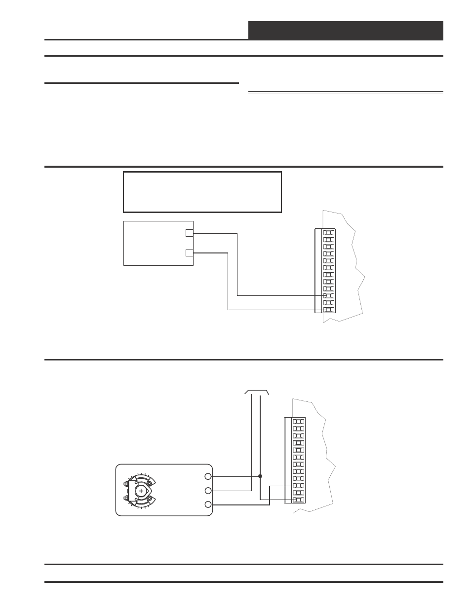
Supply Fan VFD Signal Or Zoning By-
pass Damper Actuator
The Supply Fan VFD or Zoning Bypass Damper Actuator Signal is a 0-
10 VDC
output. This signal output can be connected to the Supply Fan Variable
Frequency Drive to modulate the Supply Fan speed and control Duct
Static Pressure utilizing the Duct Static Pressure Sensor connected to
the VCM controller board. Alternatively it can be connected to a Zon-
ing Bypass Damper Actuator which will modulate the Zoning Bypass
Damper Actuator to control Duct Static Pressure utilizing the Duct Static
Pressure Sensor connected to the VCM controller board. A Duct Static
+
Supply Fan Variable Frequency Drive
(By Others)
_
VFD 0-10VDC Input
GND
Caution:
The VFD Unit Must Be Configured For 0-10 VDC Input.
The Input Resistance At The VFD Must Not Be Less
Than 1000 Ohms When Measured At The VFD
Terminals With All Input Wires Removed.
GND
INPUTS
GND
AOUT1
AOUT2
GND
+VDC
AIN1
AIN2
AIN3
AIN4
AIN5
AIN7
OE331-21-VCM
VCM Controller Board
Bypass Damper Actuator
(Belimo Actuator Shown)
0-10 VDC
24 VAC Power Source
Sized For Actuator VA Load
GND
24 VAC
Y1 3
Y1 3
+ 2
+ 2
COM -
1
COM -
1
GND
INPUTS
GND
AOUT1
AOUT2
GND
+VDC
AIN1
AIN2
AIN3
AIN4
AIN5
AIN7
OE331-21-VCM
VCM Controller Board
Belimo Actuator Wiring
Shown. Consult Factory For
Other Manufacturers Wiring
Instructions
Pressure Sensor must be connected in order for the VFD or Zoning
Bypass Damper Actuator to operate. See Figure 17 and Figure 18 for
detailed wiring.
Caution:
Variable Frequency Drive units can cause
large transient noise spikes which can cause
interference to be propagated on other
electronic equipment. Use shielded wire
wherever possible and route all sensor and
controller wiring away from the Variable
Frequency Drive and the HVAC Unit electrical
Figure 17: Supply Fan VFD Signal Wiring
Figure 18: Zoning Bypass Damper Signal Wiring