Expansion board installation & wiring, Vcm controller technical guide 11, Jumper settings – Orion System VCM Controller User Manual
Page 11: Philips
VCM Controller
Technical Guide
11
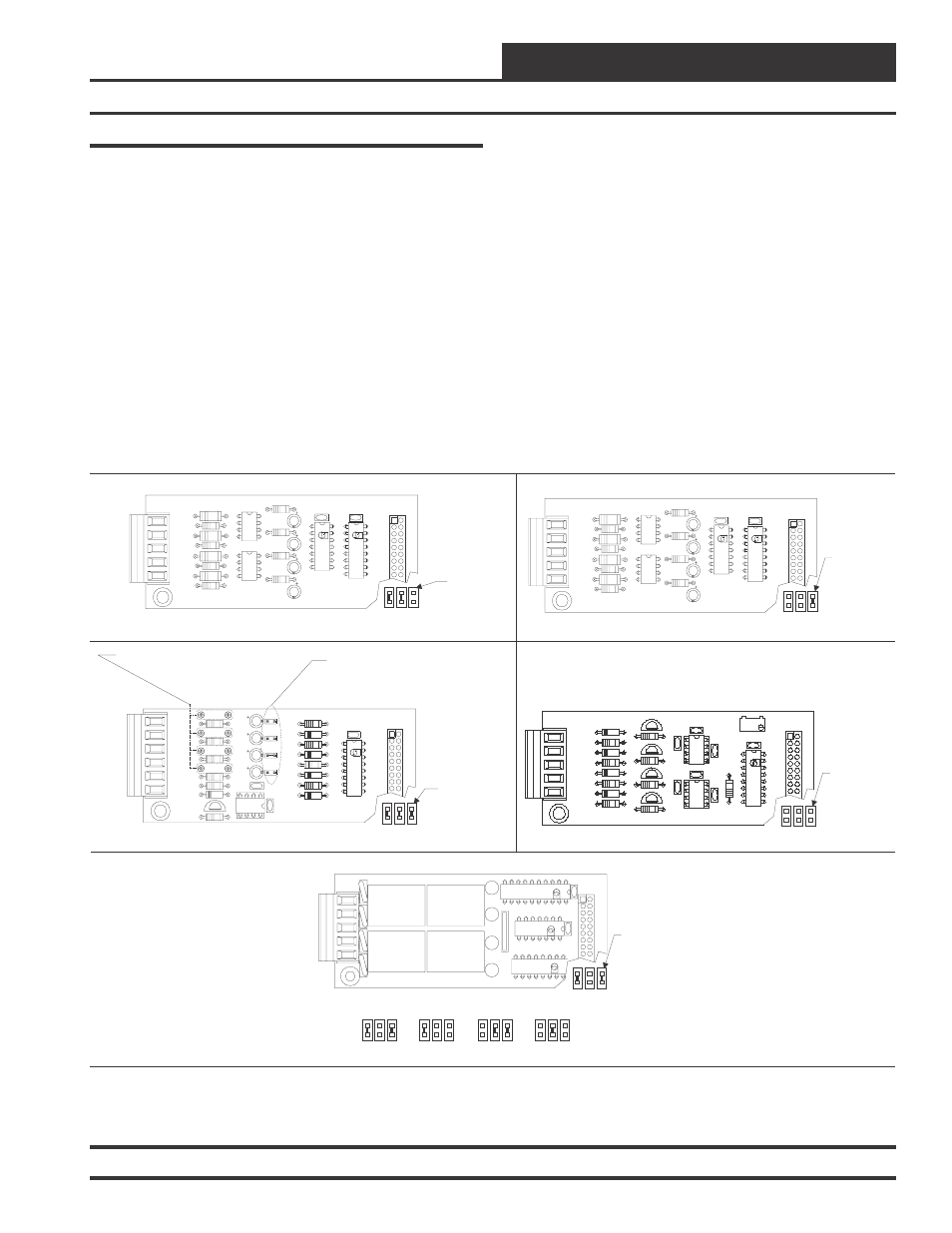
Figure 6: Expansion Board Jumper and Pullup Resistor Settings
Jumper Settings
Several different Expansion Boards are available for use with the VCM
Controller to provide additional inputs and outputs beyond those found
on the VCM Controller board. These Expansion Boards are mounted to
either the OE352, 2 slot Expansion Base Board(s) or the OE353, 4 slot
Expansion Base Board(s) depending on the total number of expansion
boards to be used with your particular application.
The OE352 2 Slot Expansion Base board or the OE353 4 Slot Expan-
sion Base boards are connected to the VCM Controller and to each
other with modular cables. A maximum of (2) Expansion Base Boards
total, (4 slot, 2 slot or a combination of both) can be connected to the
VCM controller.
The VCM controller uses the following expansion boards. The maxi-
mum quantities of each expansion board that can be used for each VCM
controller are also listed.
OE354
4 Analog Input 1 Analog Output Expansion Board
(1 per VCM Controller)
OE355
4 Analog Output Expansion Board
(1 per VCM Controller)
OE356
4 Binary Input Expansion Board
(Up to 2 boards per VCM Controller)
OE357
4 Relay Output Expansion Board
(Up to 4 boards per VCM Controller)
The various Expansion Boards can be mounted on the Expansion Base
Board in any order, however, the address jumpers located near each
Expansion Board plug-in socket must be set correctly for the Expan-
sion Board that is connected to that socket. In addition the OE354, 4
Analog Input 1 Analog Output Expansion Board also has Voltage Jump-
ers (J01, J02, J03 & J04) and Pullup Resistors (PU1, PU2, PU3, &
PU4) that must be correctly configured for proper Expansion Board
operation. See Figure 6 for the correct address jumper, voltage jumper
and Pullup resistor settings for the VCM application.
Expansion Board Installation & Wiring
JO3
JO4
JO2
JO1
CX2
R10
AOUT1
AIN4
TB1
GND
AIN2
AIN3
AIN1
PU4
U2
D5
Q1
R8
R9
LM358
C5
C1
R7
R6
R5
PU3
C4
C3
C2
PU2
PU1
4 ANALOG IN MOD. I/O BD.
R3
PCF8591P
YS101784
D4
R4
D3
D1
D2
R2
R1
PHILIPS
T L
HA
AN
I D
CX1
U1
P1
Jumpers
Under
Expansion
Board To Be
Set As Shown
Jumpers
Under
Expansion
Board To Be
Set As Shown
Jumpers
Under
Expansion
Board To Be
Set As Shown
Jumpers
Under
Expansion
Board To Be
Set As Shown
OE354 4 Analog Input - 1 Analog Output Expansion Board
OE355 4 Analog Output Expansion Board
OE356 4 Binary Input Expansion Board #2
OE356 4 Binary Input Expansion Board #1
R4
R4
R3
R3
R2
R2
R1
R1
YS101788
YS101788
BIN 4
BIN 4
BIN 3
BIN 3
BIN 2
BIN 2
BIN 1
BIN 1
COM
COM
TB1
TB1
OPTO2
OPTO2
R10
R10
R12
R12
4 DIG. IN MOD. I/O BD.
4 DIG. IN MOD. I/O BD.
P2506-2
P2506-2
R8
R8
R6
R6
R5
R5
P2506-2
P2506-2
OPTO1
OPTO1
74HC14N
74HC14N
PCF8574P
PCF8574P
U2
U2
C4
C4
C3
C3
U1
U1
CX2
CX2
C2
C2
C1
C1
CX1
CX1
P1
P1
Jumper On = 0-10VDC Input Setting
For Proper Operation Pullup Resitors PU1, PU2,
PU3 & PU4 Must Be Removed As Shown
Address Jumpers
Address Jumpers
Address Jumpers
Address Jumpers
Jumper Must Be Off For AIN1, 2 & 4
Jumper Must Be ON For AIN3
Jumper Off = 0-5 VDC Input Setting
GND
AOUT1
YS101786
4 AOUT MOD. I/O BD.
CX1
U1
Q1
LM358
R2
U2
R9
D1
R6
D2
R7
D4
D3
R8
TB1
CX2
C3
C1
P1
RV
1
R1
C4
U3
C2
LM358
CX3
AOUT2
AOUT3
AOUT4
Q2
R3
Q4
Q3
R4
R5
Jumpers
Under
Expansion
Board To Be
Set As Shown
OE357 4 Relay Output Expansion Board
UL5A250V
AC
G5L-114P
-PS
OMRON
CONTACT
:
24VDC
UL5A250V
AC
G5L-114P
-PS
OMRON
CONTACT
:
24VDC
UL5A250V
AC
G5L-114P
-PS
OMRON
CONTACT
:
24VDC
UL5A250V
AC
G5L-114P
-PS
OMRON
CONTACT
:
24VDC
K3
K2
4RLY IO BD.
V4
K4
YS101790
TB1
V1
K1
K3
U2
K4
RN1
PCF8574P
U1
T L
HA
AN
I D
ULN2803A/
K2
K1
74HC04N
PHILIPS
P1
CX2
CX1
Relays 6-9
Relays 10-13
Relays 14-17 Relays 18-21
Address Jumpers