Confi guring the pt-link dip switches – Orion System PT-Link II BACnet2 User Manual
Page 9
PT-Link II Interface
PT-Link II BACnet
®
Technical Guide
9
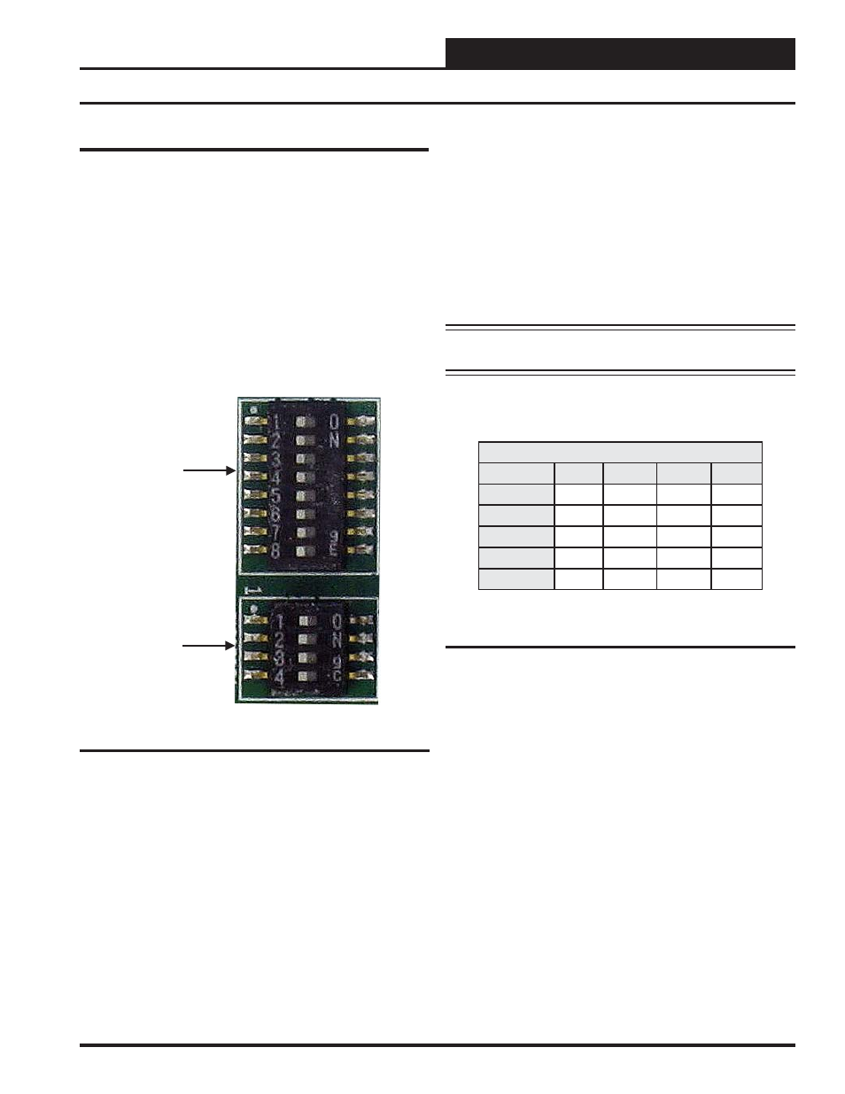
Confi guring the PT-Link DIP Switches
PT-Link DIP Switch Confi guration
If the BACnet address doesn’t need to be any higher than 255, then
follow these directions to use the DIP Switch settings to confi gure your
PT-Link II. The DIP Switches are shown in Figure 9.
The confi g.csv fi le’s ‘Server_DIP’ parameter will default to ‘Enabled’
which will allow the System_Node_ID (BACnet MAC Address) and
Node_ID (Device Instance) to be set using the DIP Switches on the
module. See Figure 17 on page 12. With this capability, RUINET is
not needed for the initial confi guration. Set the DIP Switches, power up
the PT-Link II, wait 4 minutes, and your PT-Link II BACnet is ready.
FFP-485
DIP
Switch
Bank A
DIP
Switch
Bank B
Figure 9: DIP Switches
Using B1 – B4 to Set Baud Rate
Baud
B4
B3
B2
B1
9600
ON
ON
ON
ON
19200
ON
OFF
OFF
OFF
38400
ON
OFF
ON
ON
57600
ON
ON
OFF
OFF
76800
ON
ON
OFF
ON
The DIP Switches allow you to set the Baud Rate, Node-ID (Device
Instance), and MAC address on the Field RS-485 protocol as well as to
automatically download confi guration fi les for certain protocols.
The DIP Switches are designated by Bank A & B. Bank A is used to
select both the MAC Address and Device Instance – if using the DIP
switches these will always be the same. The maximum legal value is
255. See Appendix C for each possible combination for the addresses.
Bank B is used to set the Server Baud rate. For setting serial fi eld pro-
tocol baud rate, the DIP Switches B1 – B4 can be set for the following
speeds. See Table 2 for Server Baud rate settings.
NOTE:
You must cycle power after making changes to the DIP
Switch Settings for the settings to take effect.
Table 2: Baud Rate Settings
Revised 4/25/11