Appendix g - sa controller bacnet parameters, Pt-link ii bacnet, Technical guide pt-link ii interface 50 – Orion System PT-Link II BACnet2 User Manual
Page 50
PT-Link II BACnet
®
Technical Guide
PT-Link II Interface
50
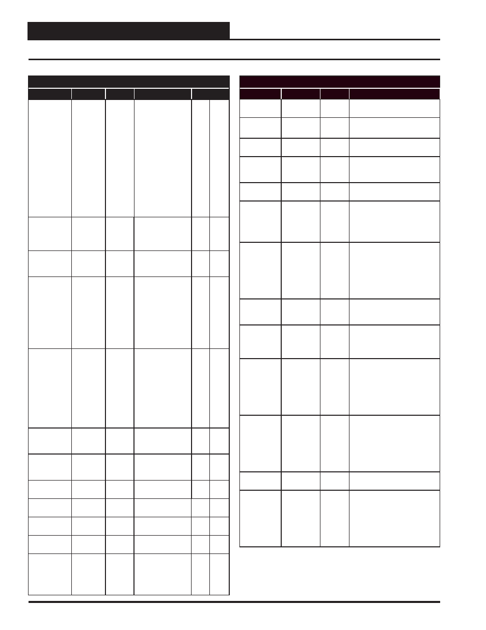
Appendix G - SA Controller BACnet Parameters
BACnet Properties for SA Controller
Parameter
Name
Object
Description
Limits
Unoccupied
Heating
Offset
UnHtOst
AV: 125
During the
Unoccupied Mode
of Operation, this
Setpoint spreads
the Occupied
Heating Setpoint
out by a user
adjustable amount.
If you do not want
Heating to operate
during the Unoc-
cupied Mode, use
the default setting
of 30°F for these
setpoints.
0
30
Static
Pressure
Setpoint
DuctPrSt
AV: 152
This is the target
duct pressure to be
maintained by the
VFD blower signal.
0.01
3
Preheater
Setpoint
PreHtSp
AV: 196
Low Outside Air
Ambient
Protection Setpoint
0
100
Entering
Air Offset
Setpoint
EaTpOst
AV: 238
If the Entering
Air Temperature
Sensor is reading
incorrectly, you
can use this option
to enter an offset
temperature to
adjust the Sensor’s
Temperature.
Entering
Water
Offset
Setpoint
EwTpOst
AV: 239
If the Entering
Water Temperature
Sensor is reading
incorrectly, you
can use this option
to enter an offset
temperature to
adjust the
Sensor’s
Temperature.
Supply Air
Cool High
Reset
SaClRt
AV: 324
High Supply Air
Cooling Reset
Limit
40
150
Supply Air
Heat High
Reset
SaHtRt
AV: 325
High Supply Air
Heating Reset
Limit
40
150
Cooling Low
Reset Source
ClLoRt
AV: 326
Low Cool Reset
Source Setpoint
1
150
Cooling High
Reset Source
ClHiRt
AV: 327
High Cool Reset
Source Setpoint
1
150
Heating Low
Reset Source
HtLoRt
AV: 328
Low Heat Reset
Source Setpoint
1
150
Heating High
Reset Source
HtHiRt
AV: 329
High Heat Reset
Source Setpoint
1
150
Fan Start Up
Delay
FanDly
BI: 25
Status that indicates
the fan is com-
manded to run, but
it is in the start up
delay mode.
BACnet Properties for SA Controller
Parameter
Name
Object
Description
Bad Supply
Air Sensor
SaTpAlm
BI: 2
Alarm that indicates a failure in
the supply air sensor.
Cooling
Enabled
ClEnbl
BI: 6
Status that indicates
mechanical cooling is enabled.
Economizer
Enabled
EcoEnbl
BI: 15
Status that indicates
the economizer is enabled.
Fan
Proving
Alarm
PofAlm
BI: 26
Alarm that indicates a failure in
the fl ow of the VFD blower.
Heating
Enabled
HtEnbl
BI: 30
Status that indicates that me-
chanical heating is enabled.
High
Supply Air
Temperature
Alarm
HiSaAlm
BI: 33
The Supply Air has risen above
the Hi SAT Cutoff Setpoint.
Heating stages begin to
deactivate and the fan continues
to run.
Low Supply
Air
Temperature
Alarm
LoSaAlm
BI: 37
The Supply Air has fallen below
the Hi SAT Cutoff Setpoint and
cooling stages will begin to
deactivate. If the unit is in
Economizer, Vent, or Heating
Mode the Supply Fan
will shut off.
MODGAS II
Connected
MdHt2Ins
BI: 39
Status that indicates
the MODGAS II controller is
connected.
REHEAT II
Connected
Rt2Ins
BI: 58
Status that indicates
the MHGRV
controllers is connected to the
system.
Mechanical
Cooling
Alarm
MchClAlm
BI: 94
Compressor Relays are enabled
but the Supply Air Temperature
has not fallen 5°F w/in a user-
adjustable time period. This does
not indicate compressors are
active and will not
shut the unit down.
Mechanical
Heating
Alarm
MchHtAlm
BI: 95
Heating Mode has been initiated
but the Supply Air Temperature
has not risen 5°F w/in a
user-adjustable time period.
This does not indicate heat
stages are active and will not
shut the unit down.
Dirty Filter
Detected
DrtFlAlm
BI: 96
Alarm that indicates the fi lters
are dirty.
Control
Temperature
Cool Failure
CtrlTpCF
BI: 108
This alarm is activated if the
control temperature does not
get within 5°F to the occupied
cooling setpoint in an hour in the
cooling mode. This alarm is not
used in 100% outside air units or
supply air control.
Revised 4/3/13