Appendix d - vcb-x bacnet parameters, Pt-link ii bacnet, Technical guide pt-link ii interface 34 – Orion System PT-Link II BACnet2 User Manual
Page 34
PT-Link II BACnet
®
Technical Guide
PT-Link II Interface
34
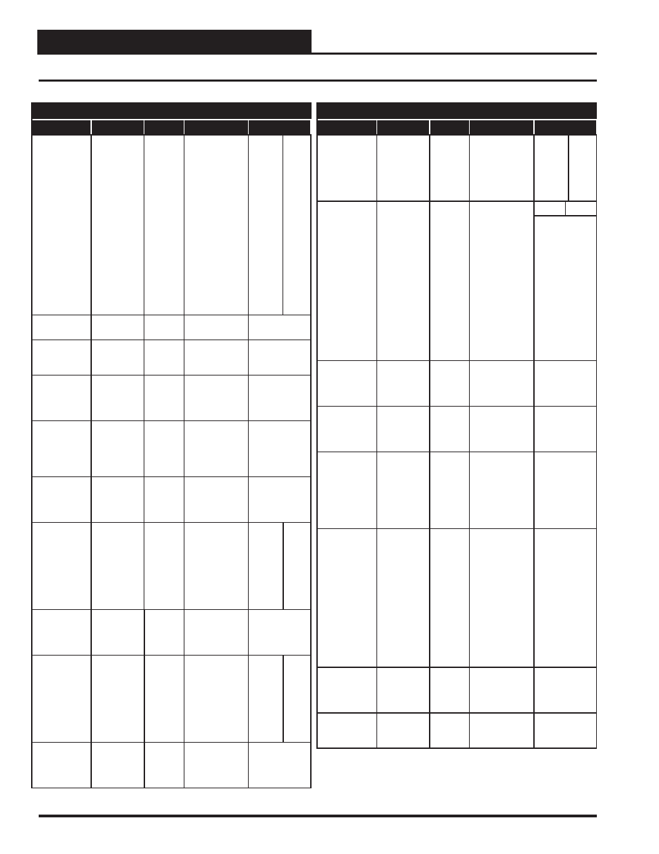
Appendix D - VCB-X BACnet Parameters
BACnet Properties for the VCB-X Controller
Parameter
Name
Object
Description
Limits
Low Coil
Temperature
Setpoint
LoClTpSt
AV:295
This is the
lowest that the
Coil
Temperature
will be reset to
during Space
Humidity Reset
of the Coil
Suction
Temperature
Setpoint.
Produces a
dewpoint in
the supply air
approximately
10˚F above this
setpoint.
35
70
Condenser
Control Signal
CdCtrSg1
AI:280
Condenser Fan
Signal 1 Status.
Control Status
CtrlSts
AI: 4
Current
operational
status.
See Control
Status Bits on
page 39.
Control
Temperature
CtrlTp
AI: 9
Current value
of the control
temperature
sensor.
Cooling
Enabled
ClEnbl
AI: 6
Status that
indicates
mechanical
cooling is
enabled.
Cooling
Setpoint
Mirror
ClSt
AI: 7
Occupied
Cooling Mode
Enable
Setpoint Mirror.
Dewpoint
Setpoint
RhDewpSt
AV:282
On a MUA unit,
if the outdoor
dewpoint rises
above this
setpoint, the
unit will
activate Dehu-
midifi cation.
35
80
Economizer
Enabled
EcoEnbl
AI: 15
Status that
indicates
the economizer
is enabled.
Economizer
Enable
Setpoint
EcoEnbSt
AV:283
The economizer
is enabled if the
outdoor dry-
bulb, dewpoint,
or wetbulb
temperature
falls below this
setpoint.
-30
80
Economizer
Position
EcoPos
AI: 16
Current
position of the
economizer
damper.
BACnet Properties for the VCB-X Controller
Parameter
Name
Object
Description
Limits
Minimum
Economizer
Position
MinEcoSt
AV: 151
This is the
minimum
position of the
economizer in
the occupied
mode.
0
100
Force
Economizer
FrcEcono
AV: 267
Overrides all
other Outdoor
Air Damper
position com-
mands so as to
maintain this
fi xed position.
Confi guring
for “Auto” will
restore normal
unit control of
the Outdoor
Air Damper/
Economizer
operation.
0%
100%
Auto=65535
Exhaust Fan
CFM
EtCFM
AI:194
Current
Exhaust
Airfl ow
Measurement
Exhaust Fan
Speed
EtFnSpd
AI: 273
Current
position of the
VFD relief
fan signal.
Fan
Starting Delay
FanDly
AI: 25
Indicates the
current fan
status related
to request to
run, fan starting
delay or POF
failure.
0=No Request
1=Fan
Running
2=Fan Start
Delay
3=POF Failure
Force HVAC
Mode
FrcHvacM
AV: 262
Overrides
normal control-
ler operation in
order to force
the unit into
this desired
mode. Con-
fi guring for
“Auto” will
restore normal
unit control of
the mode of
operation.
0=Auto
1=Vent
2=Cool
3=Heat
4=Vent
Dehum.
5=Cool
Dehum.
6=Heat
Dehum.
Head
Pressure
HeadPr
AI:276
Current value
of the Head
Pressure
Reading.
Head
Pressure
Setpoint
HeadPrSt
AI:279
Current Head
Pressure
Setpoint.
Revised 1/20/12