Installation and wiring, Rne modular controller field technical guide 46, Two condenser head pressure ii module – Orion System RNE Modular Controller User Manual
Page 46: Zone, Hssc cable, Condenser signal 2, Condenser signal 1, Condenser fan 1 ecm motor, Condenser fan 2 ecm motor
Zone
Zone
INSTALLATION AND WIRING
RNE Modular Controller Field Technical Guide
46
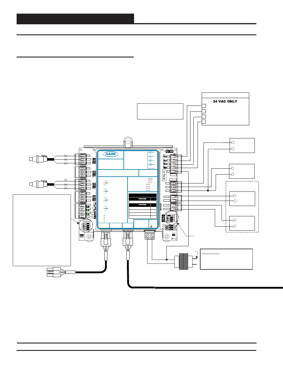
Figure 37: RNE 120 - 140 Ton Unit Four Compressor Two Condenser Head Pressure II Module Wiring
RNE 120 - 140 Ton Unit Compressor and Condenser Wiring
Two Condenser Head Pressure II
Module
For RNE 120 - 140 Ton units, (2) Two Condenser Head Pressure II
Modules ( OE370-23-HP2C2) will be used to monitor four head pressure
transducers and control four condenser fans or water valves (two circuits
per module). A pulse width modulation (PWM) signal or a 0-10 VDC
output signal is used to control these condenser devices. See Figure 37
below and on page 47 for the wiring details.
The Two Condenser Head Pressure II Modules are connected together
and then back to the Full Digital Module, a Water Source Heat Pump
Module, or the RNE Controller with HSSC cables. This allows setpoints,
status values, and alarms to be communicated between the RNE Con-
troller and the Two Condenser Head Pressure II Modules. This module
requires a 24 VAC power connection with an appropriate VA rating.
SIG
GND
+V
BK
RD
WH
SIG
GND
+V
BK
RD
WH
Head Pressure Transducers 1 - 2
0 - 667 PSI
(One Per Refrigerant Circuit)
OE370-23-HP2C2
Two Condenser Head Pressure II ModuleI
OPTIONS Dip Switch Setting Not
Required When Connected To
RNE Controller.
+5V
SIG 2
GND
OP
T
IO
N
S
ALARM
ANALOG
STAT
+5V
COMM
GND
SIG 4
GND
R1
R2
GND
RELAYS
ADDRESS
SIG 3
+5V
GND
+5V
SIG 1
R3
R4
Rc
AO1
AO2
PWM1-
PWM1+
PWM2-
PWM2+
PWR
Connect To
Full Digital Module
Connect To 2nd
Two Condenser Head
Pressure Module
HSSC Cable
24 VAC Transformer
3 VA Minimum
Line Voltage
24 V
A
C
GND
WARNING!! Observe Polarity! All
boards must be wired with GND-to-
GND and 24 VAC-to-24 VAC.
Failure to observe polarity could
result in damage to the boards.
NOTE:
NORMALLY OPEN AND
RATED FOR 24 VAC POWER
ONLY
ALL RELAY OUTPUTS
ARE
- 1 AMP MAXIMUM LOAD
HSSC Cable
Set ADDRESS Dip Switch 1 to ON for
Water Cooled or to OFF for Air Cooled.
Currently showing OFF for Air Cooled.
If Using (2) Modules, Set ADDRESS
Dip Switch 2 to OFF on the 1st Module
and to ON on the 2nd Module.
Currently showing OFF.
Set ADDRESS Dip Switch 3 to ON to
disable Circuit B alarms when only one
Condenser is used. Currently showing
OFF.
Set ADDRESS Dip Switch 4 to OFF to
make reversing valve "ON to Heat /
OFF to Cool.” Set to ON to make
reversing valve “ON to Cool / OFF to
Heat.” Currently showing OFF.
BIN 1
BIN 2
BIN 3
COM
COM
+
Condenser
Signal 2
COM
+
Condenser
Signal 1
CONDENSER 1 ENABLE
R1
HVAC UNIT CONNECTION
R3
CONDENSER 2 ENABLE
COMM
REVERSING VALVE 2 ENABLE
REVERSING VALVE 1 ENABLE
R4
R2
+24 Volts
Condenser Fan 1
ECM Motor
Duty Cycle
Condenser Fan 2
ECM Motor
YELLOW
BLUE +24 OUT
+24 Volts
Duty Cycle
YELLOW
BLUE +24 OUT
LED BLINK CODES
LED NAME
STAT
BLINKS QTY. OF SENSORS INSTALLED
LED NAME
ALARM
NO PROBLEMS
0
NO SENSORS DETECTED
1
HIGH HEAD PRESSURE DETECTED
2
LOW HEAD PRESSURE DETECTED
3
WattMaster Label
#LB102110-A
Rev.: 1A
E-BUS
Connector
E-BUS
Connector
+5V
SIG 1
GND
+5V
SIG 2
GND
+5V
SIG 3
GND
+5V
SIG 4
GND
+24
VAC
GND
BIN 1
BIN 2
BIN 3
COM
HEAD
PRESSURE
TRANSDUCER #1
HEAD
PRESSURE
TRANSDUCER #2
HEAD
PRESSURE
TRANSDUCER #3
HEAD
PRESSURE
TRANSDUCER #4
REV. VLV. ENABLE INPUT
COMMON
PWM2+
AAON No.:
V20660
AO1
AO2
GND
COND. A ENABLE INPUT
COND. B ENABLE INPUT
COND. A SIGNAL
COND. B SIGNAL
PWM1-
PWM1+
PWM2-
COND. FAN A
COND. FAN B
COND. FAN A
COND. FAN B
GND
Two Condenser Head Pressure II Module
2C2
Orion No.:OE370-23-HP
www.aaon.com
RELA
Y
C
ONT
A
CT
RA
TING
IS
1
A
MP
MAX
@
24
V
A
C
COND. A ENABLE
COND. B ENABLE
REV. VLV. A ENABLE
REV. VLV. B ENABLE
R1
R2
R3
R4
RC
RELAY COMMON
A1
A2
B1
B2