Installation and wiring, Rne modular controller field technical guide, Wshp-x2 module – Orion System RNE Modular Controller User Manual
Page 41
RNE Modular Controller Field Technical Guide
INSTALLATION AND WIRING
41
Connect To
RNE Controller
WARNING!! Observe Polarity! All
boards must be wired with GND-to-
GND and 24 VAC-to-24 VAC.
Failure to observe polarity could
result in damage to the boards.
HSSC Cable
Connect To Two Condenser Head
Pressure II Module
WATTMASTER CONTROLS
Y 102374 REV 0
S
MADE IN USA
OE334-26-WSHP-X2
Water Source
Heat Pump X2 Module
NOTE:
NORMALLY OPEN AND
RATED FOR 24 VAC POWER
ONLY
ALL RELAY OUTPUTS
ARE
COMP. 2 ENABLE
COMP. 1 ENABLE
R1
R5
R3
COMM
ALARM OUTPUT
HVAC UNIT
CONNECTIONS
24 VAC Transformer
3 VA Minimum
Line Voltage
24 V
A
C
GND
WARNING!!
Observe Polarity! All
boards must be wired
with GND-to-GND and 24
VAC-to-24 VAC. Failure
to observe polarity could
result in damage to the
boards.
HSSC Cable
GND
T1
WATER POF 1
BIN6
COM
E
LEAVING WATER
TEMPERATURE 1
T2
BIN7
WATER POF 2
SIG 2
GND
+V
BK
RD
WH
SIG 1
GND
+V
BK
RD
WH
SUCTION PRESSURE
TRANSDUCER 1
SUCTION PRESSURE
TRANSDUCER 2
AOUT1
AOUT3
WARNING!!
Observe Polarity! All
boards must be wired
with GND-to-GND and 24
VAC-to-24 VAC. Failure
to observe polarity could
result in damage to the
boards.
WattMaster Label
#S
000063
Rev.: 1B
W
E-BUS
HSSC
CONNECT
M
ENTER
UP
DOWN
ALARM
MENU
OE334-26-WSHP-X2 WSHP-X2 MODULE
AAON NO.: V48820
+24 V
A
C
GND
www.orioncontrols.com
www.aaon.com
- COMP A1 EN
- HEAT ENABLE
- COMP A2 EN
- H2O POF A
- COMP B1 EN
- H2O POF B
- COMP B2 EN
- COMMON
GND
- LEAVING WATER TEMP
- GROUND
- LEAVING WATER TEMP
AOUT1
- COMP A1
DIGITAL/VFD COMPRESSORS
A1, A2, B1, B2
RELAY CONTACT RATING
IS 1 AMP MAX @ 24 VAC
COMP. A2 ENABLE
COMP. A1 ENABLE
R1
R2
R3
R4
R5
RC
RELAY COMMON
COMP. B1 ENABLE
COMP. B2 ENABLE
ALARM OUTPUT
CONNECT TO
CNTLR C2
TERM.
+5V
PRES
GND
+5V
PRES
GND
SUCT. PR. SENSOR
PRES 1=A1, PRES 2=A2
PRES 3=B1, PRES 4=B2
NOT USED
PRES 1=A1, PRES 2=A2
PRES 3=B1, PRES 4=B2
+5 NOT USED, PRES TO P6 & GND TO P5
+5 TO RED, PRES TO WHT & GND TO BLK
DIGITAL COMRESSORS
NON-DIGITAL COMPRESSORS
AOUT2
- COMP A2
AOUT3
- COMP B1
AOUT4
- COMP B2
E-BUS
HSSC
CONNECT
BIN1
BIN2
BIN3
BIN4
BIN5
BIN6
BIN7
COM
T 1
T 2
Compressor 1
Compressor 2
COM
+
COM
+
LEAVING WATER
TEMPERATURE 2
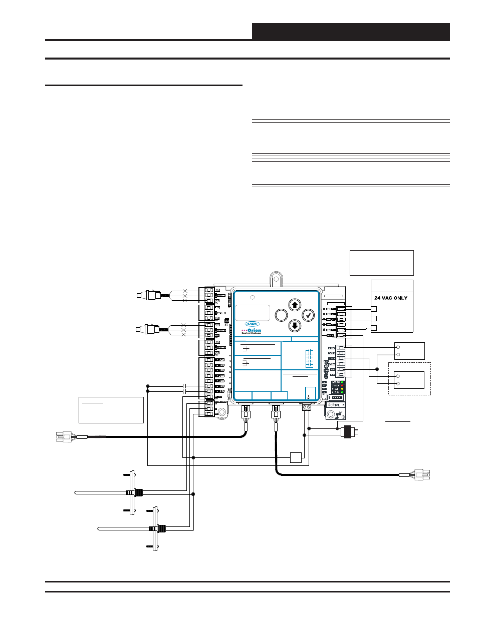
RNE 55 - 105 Ton Unit Compressor and Condenser Wiring
Figure 33: RNE 55 - 105 Ton Unit Two Compressor WSHP-X2 Wiring
WSHP-X2 Module
RNE Units with DX Cooling will have either a Half VFD/Half Fixed
compressor confi guration or a Full VFD compressor confi guration. The
RNE 55 - 105 Ton units have two compressors and will have either one
VFD and one Fixed Compressor or will have two VFD Compressors.
The operation of these compressors is described in the Sequence of
Operation section of this manual.
On Water Source Heat Pump (WSHP) units, the outputs to the compres-
sors will always be wired from the WSHP-X2 Module. Each compressor
will need to have a relay confi gured and wired from this module, and the
VFD output(s) will be wired from this module. The Suction Pressure
Transducer for each compressor and the Proof of Flow switch for each
water circuit will also be wired into this module. See Figure 33 below
for the wiring diagram. The WSHP-X2 Module monitors conditions on
the unit and can disable compressors based on Low Suction Pressure,
Low Leaving Water Temperature, or a loss of Water Proof of Flow. It
also utilizes a Delay Timer to prevent the compressors from turning on
at the same time.
The WSHP-X2 Module connects to the RNE Controller or the Two
Condenser Head Pressure II Module with an HSSC Cable. This allows
setpoints, status values, and alarms to be communicated between the
RNE Controller and the WSHP-X2 Module. This module requires a 24
VAC power connection with an appropriate VA rating.
NOTE: The Compressor Relays on the WSHP-X2 Module are
used rather than the relay outputs on the RNE
Controller.
NOTE: For more information, see the WSHP-X2 Module Field
Technical Guide.