6 index speed considerations, Index speed considerations – MicroE Mercury II 5000 User Manual
Page 33
Appendix
IM-Mercury_II_5000_Series Rev. 1
Page 32
©2014 MicroE Systems
Mercury II 5000 Series Encoders
Installation Manual and Reference Guide
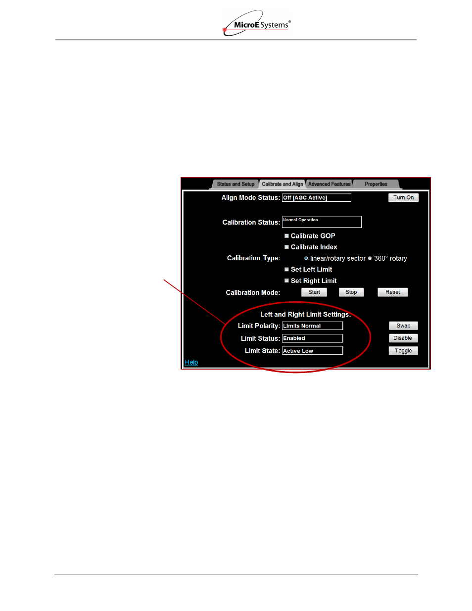
Left and Right Limit Settings can be changed by clicking on the associated controls
(Swap, Enable/Disable, and Toggle):
o Limit Polarity: Normal - left limit marker triggers left limit signal; right limit marker
triggers right limit signal. Reversed - left limit marker triggers right limit signal;
right limit marker triggers left limit signal.
o Limit Status: The limits may also be enabled or disabled.
o Limit State: Active High - status bit = 1 when limits is active; Active Low - status
bit = 0 when limit is active.
See examples in Calibrate and Align screen below.
Performance Specifications
Resolution: 5µm to approximately 1.22nm
Maximum travel before position counter rollover, with fringe count bits set to 21: 41.94304
meters
Maximum speed: 10m/s
Maximum cable length: 10m
6.6
Index Speed Considerations
MII5000
Maximum Speed for MII5000 Index after Power-up (MII5800, MII5700 and MII5500 Models):
Each time an MII5800, MII5700, or MII5500 encoder is powered up, the first pass over the index
mark must occur at a speed
≤1m/s. Once the index is initially detected, the index will function at
all speeds (up to 10m/s) until the next power cycle.
Limit Settings