MicroE Mercury II 5000 User Manual
Page 29
Appendix
IM-Mercury_II_5000_Series Rev. 1
Page 28
©2014 MicroE Systems
Mercury II 5000 Series Encoders
Installation Manual and Reference Guide
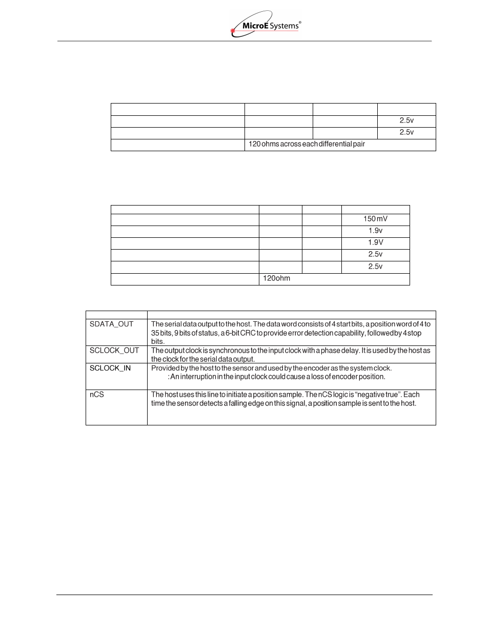
Output Signal Specifications
SDATA_OUT
SCLOCK_OUT
Parameter
Minimum
Typical
Maximum
Differential Output Voltage
500 mv
2v
Common Mode Output Voltage
500 mv
2v
Termination
Input Signal Specifications
SLOCK_IN
nCS
Parameter
Minimum
Typical
Maximum
Differential Output Voltage
Common Mode Output Voltage
1.1v
1.6v
Absolute Maximum Single-Ended Voltage
-0.3V
2v
Recommended Common Mode Voltage
1.2v
2v
Recommended Differential Input Voltage
250 mv
2v
Impedance
Signal Definitions
Signal
Definition
Note
Clock frequency requirements: 30MHz to 50MHz
Maximum position sample frequency (falling edge to falling edge): 220 clock cycles
Minimum Pulse Width (high or low): 2 clock cycles
Power-Up Sequence
Power is supplied from the host to the sensor. After power is supplied, the following sequence is
performed:
The sensor waits for the serial clock to be provided by the host on the signal SCLOCK_IN
for 100ms.
If a clock is not provided, the sensor switches to operate in the final mode (quadrature or
serial).
Upon detecting a serial clock on SCLOCK_IN, the sensor returns the clock to the host on
SCLOCK_OUT.
Within the first 500ms after the serial clock is provided by the host, SCLOCK_OUT may
be unstable.