MicroE Mercury II 5000 User Manual
Page 27
Appendix
IM-Mercury_II_5000_Series Rev. 1
Page 26
©2014 MicroE Systems
Mercury II 5000 Series Encoders
Installation Manual and Reference Guide
Signal Wiring for Serial Interface
Each differential signal should be connected to a corresponding twisted pair as follows:
Note: NC - No Connect
Shield Termination
The customer's cable shield must be in 360° contact with the connector shroud and the
connector shell to provide complete shielding.
The connector shell should be metal with conductive surfaces. Suggested metal
connector shells for use with Mercury II encoders: AMP 748676-1 or equivalent; where
the dash number is dependent on the customer's outside cable diameter.
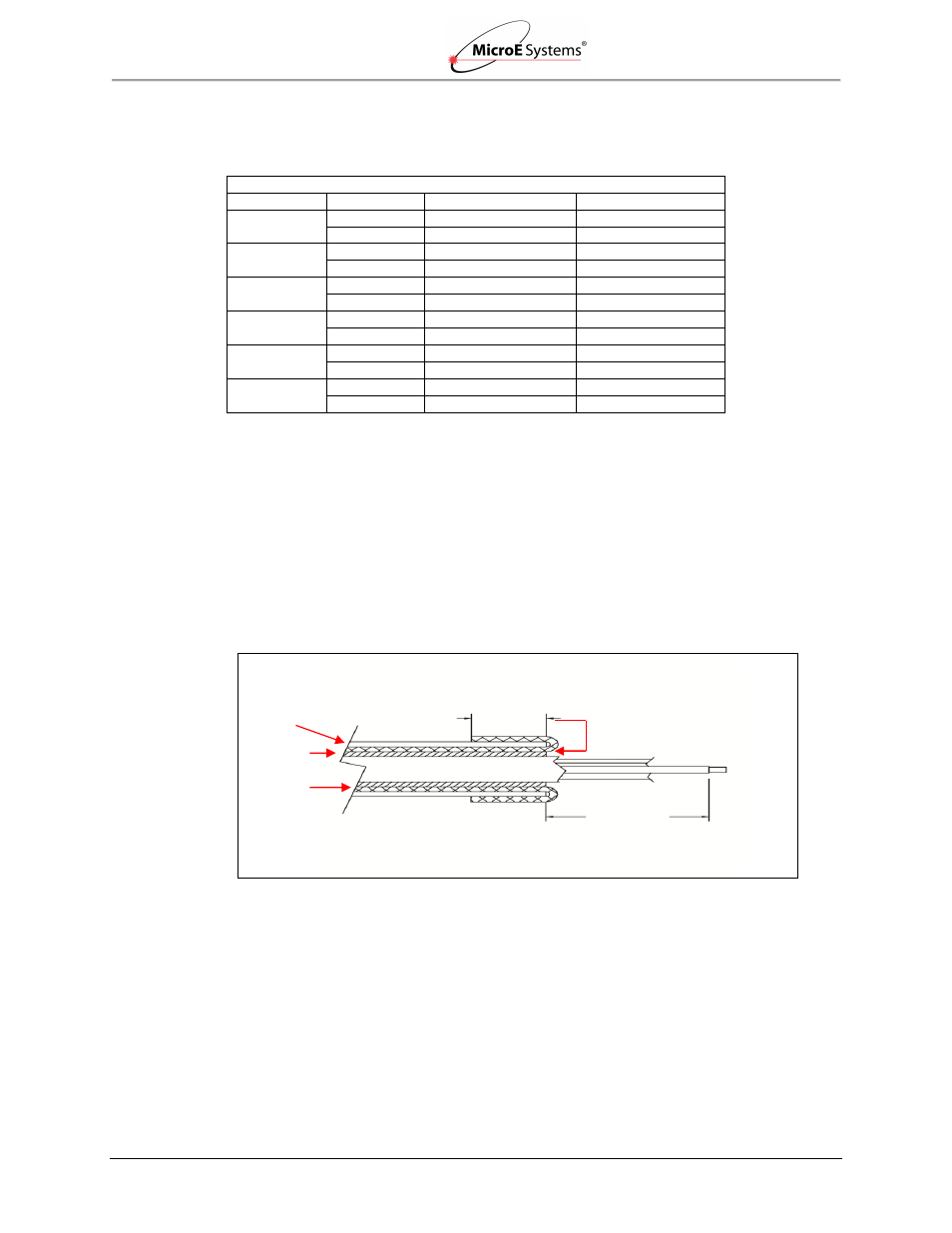
Terminate the shield as illustrated in the following diagram.
Note: Fold braided shield back over jacket. Example shows double-shielded cable. Dimensions
shown are for purpose of illustration only.
Mercury II 5800Si/Pa Signals
Twisted Pair
DB15 Pins
5800Si Signals
5800Pa Signals
Pair 1
14
SDATA_OUT+
NC*
6
SDATA_OUT-
NC
Pair 2
13
SCLOCK_OUT+
NC
5
SCLOCK_OUT-
NC
Pair 3
10
SCLOCK_IN+
REQ_SD+
11
SCLOCK_IN-
REQ_SD-
Pair 4
1
nCS+
NC
3
nCS-
NC
Pair 5
7
+5V
NC
8
+5V
NC
Pair 6
2
GND
NC
9
GND
NC
7.6 (.30)
Braided
Shield
Aluminum
Polyester
Shield
Jacket
28.7 (1.13)
Aluminum Polyester Shield not to
be exposed in this area.
Do not twist.