5 serial interface specifications, Serial interface specifications – MicroE Mercury II 5000 User Manual
Page 28
Appendix
IM-Mercury_II_5000_Series Rev. 1
Page 27
©2014 MicroE Systems
Mercury II 5000 Series Encoders
Installation Manual and Reference Guide
6.5
Serial Interface Specifications
Introduction
The serial interface to the Mercury II 5800Si/Pa allows a serial host (controller) to receive position
and status information serially from the sensor. Serial communications between the encoder and
controller permit high speed motion system operation with high encoder resolution: up to 10m/s
with the 1.2nm. The serial data word consists of the following sequence:
Position word of four start bits
Four to thirty-five position bits
Nine bits of status
Six-bit Cyclic Redundancy Check (CRC) to provide error detection
Four stop bits
The encoder’s position is sampled by the MII5800Si at the moment the host commands a sample
(falling edge of nCS); the only latency in the system is the time required for the host to receive the
position word. This architecture minimizes latency and eliminates jitter due to sampling
uncertainty.
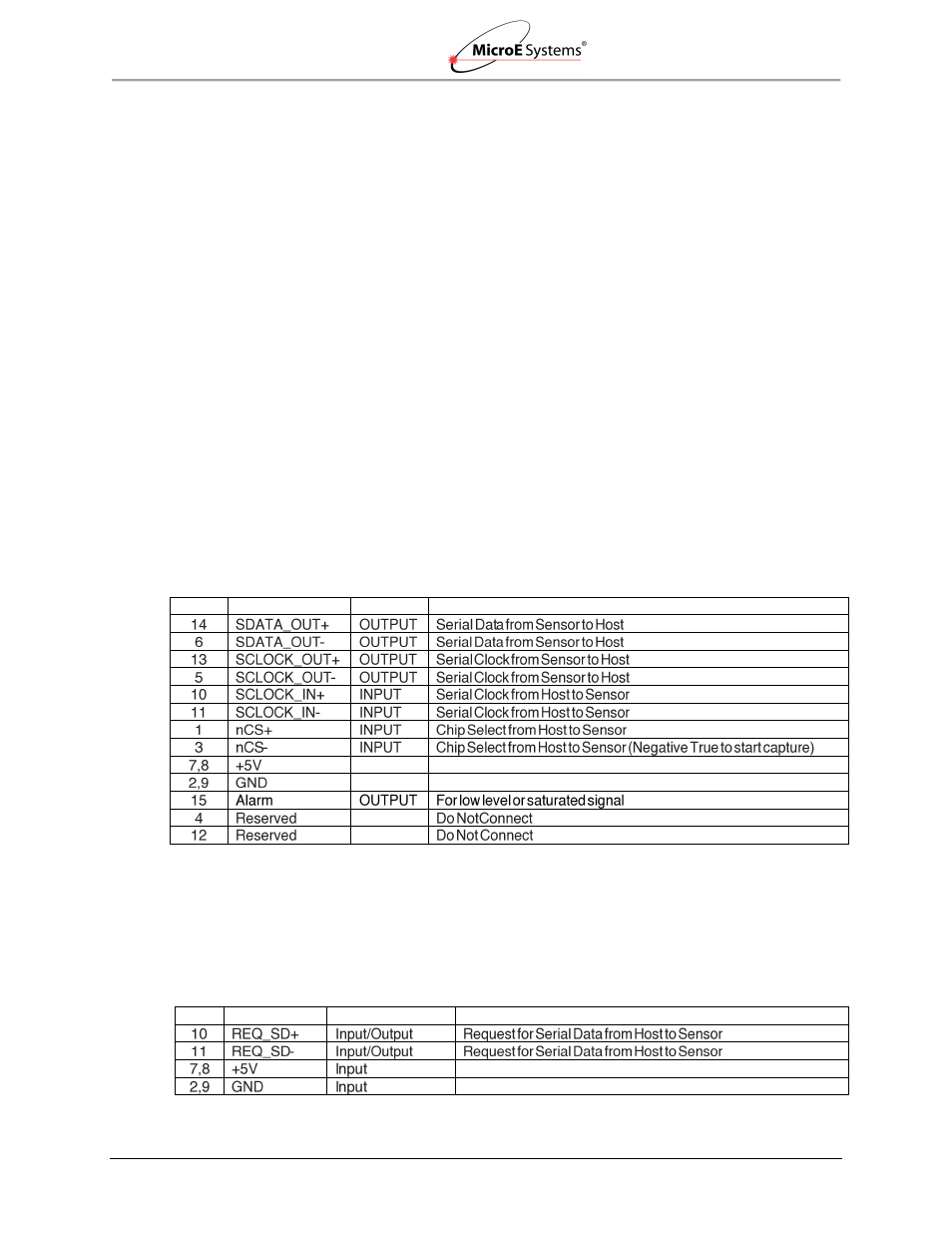
Serial Interface Input/Output
MII5800Si (Serial Interface)
Pin
Name
Direction
Description
MII5800Pa (Panasonic)
The following are the pins used by the MII5800Pa Panasonic serial interface.
Pins 2, 7, 8, 9 are the same for both MII5800Si and Panasonic
Pins 10 and 11 are different for Panasonic
All other pins for Pa are not connected (NC)
Pin
Name
Direction
Description