MicroE Mercury II 5000 User Manual
Page 11
Sensor Alignment and Calibration
IM-Mercury_II_5000_Series Rev. 1
Page 10
©2014 MicroE Systems
Mercury II 5000 Series Encoders
Installation Manual and Reference Guide
Step
Action
4.
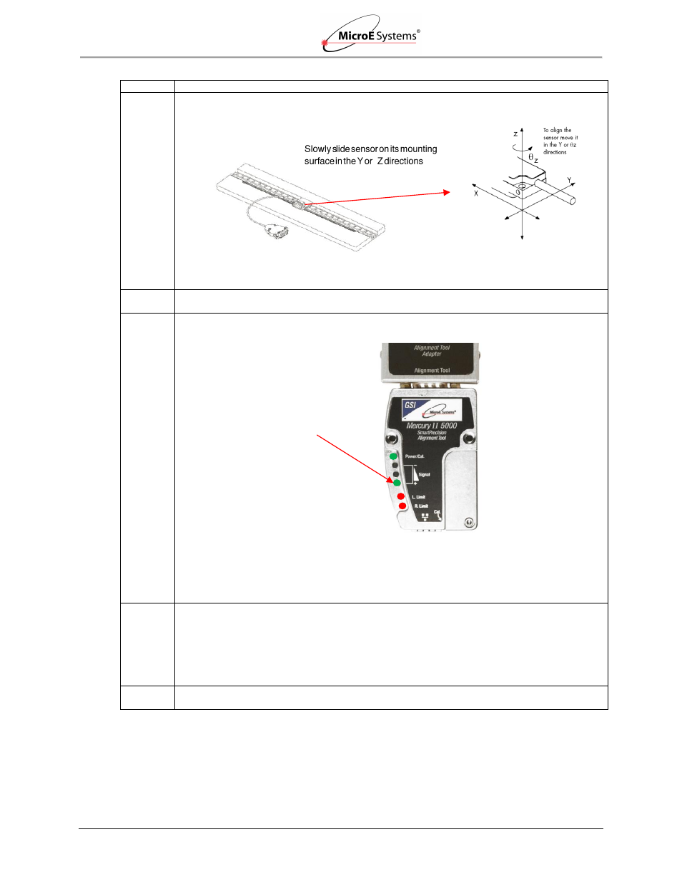
Align the sensor by slowly sliding the sensor on its mounting surface in the Y or
Z directions
until the green Signal Strength LED is illuminated*:
Note*: Optimal alignment is indicated by Bright Green.
5.
Once the sensor is aligned, tighten the two sensor mounting screws (0.37Nm [3.3 inch-lbs.]
maximum torque).
6.
Move the sensor over the index mark and confirm that the green Signal Strength LED blinks.
Result:
If the green Signal Strength LED blinks when the sensor passes over the index, then
proceed to the next step.
If the green Signal Strength LED does not blink when the sensor passes over the index,
then loosen the mounting screws and repeat the alignment procedure (go back to Step 3).
Note*: Optimal alignment is indicated by Bright Green and a blink over the index
.
7.
Move the sensor over the entire length of the scale.
Result:
If the green Signal Strength LED remains illuminated over the entire length of travel (the
yellow and red LED’s do not illuminate), then proceed to the next step.
Otherwise, clean the scale
and try Step 3 again. If cleaning the scale is not successful,
loosen the sensor mounting screws and repeat the alignment procedure (go back to
Step 3).
8.
Press and release the Cal button quickly to exit Alignment Mode.
Result: The
limit LED’s will stop blinking and AGC will reactivate.
Green Signal Strength LED
(Proper Alignment)*