Microcom 814M Operators Manual User Manual
Page 31
27
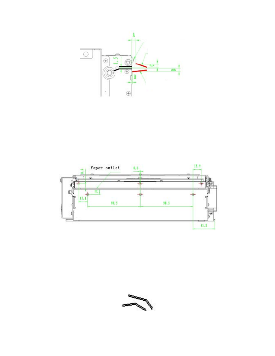
− Upper guide “A” dimension of paper out path should be controlled from 4.5 to 5.5 mm and “C”
dimension should be from 4 to 5mm.This is mainly to avoid the interference when the upper cover of
PRE uplifts, and also to avoid interference with the retaining screw (M2.5) of the PRE upper cover.
− Lower guide B dimension of paper out path is controlled to be within 1mm, and D is from 2 to 4mm.
Note:
− The paper outlet shown in figure is just a sketch map; the paper outlet angle can be designed
according to actual need. But try to avoid the paper outlet bend in order to increase the smoothness of
the paper path.
− Retaining holes are provided in the printer mechanism for connecting the paper out (see figure 4.25).
− If you need to use the retaining holes, design the size of paper out path according to above request
strictly. If your paper outlet is not assembled on the printer and the paper outlet can be separated from
the printer during maintenance, “A” and “C” dimensions are not as critical.
− To prevent paper jams in the paper outlet can be designed as shown in figure 4-26. But as a result of
the design, the paper cannot fall off automatically during paper out. You can design it in other shapes,
but try to keep the paper outlet smooth.
Figure 4-25 Retaining Holes
Figure 4-26 Paper Outlet Preventing Jammed Paper
Figure 4-24 Paper Outlet Explanation
Note this retaining screw
Paper outlet upper guide
Paper outlet lower guide