Switch & sense 8 block diagram, Software features – Measurement Computing SWITCH User Manual
Page 9
Switch & Sense 8 User's Guide Template
Switch & Sense 8 block diagram
9
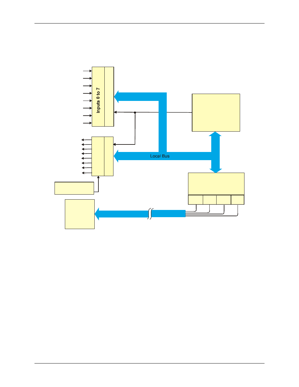
Switch & Sense 8 block diagram
Switch & Sense 8 functions are illustrated in the block diagram shown here.
USB
Controller
Control
Registers
Control
Bus
F
O
R
M
C
R
el
ay
O
ut
pu
ts
C
on
tr
ol
R
el
ay
s
0
to
7
D
iff
er
en
tia
l
Is
ol
at
ed
In
pu
ts
C
on
tr
ol
9 VDC external
power supply
9V
D+
D-
Vcc Gnd
USB
HOST
Universal Serial Bus
(1.5 MBS)
Figure 1. Switch & Sense 8 functional block diagram
Software features
The Switch & Sense 8 ships with its own software library which you can use to configure, test, and control this
USB device. Install the software before installing the Switch & Sense 8.
This manual is related to the following products: