Usb connection, Read/write benchmark timing, Environmental – Measurement Computing SWITCH User Manual
Page 32: Mechanical, Screw terminal, Miscellaneous, Screw terminal pinouts
Switch & Sense 8 User's Guide Template
Specifications
32
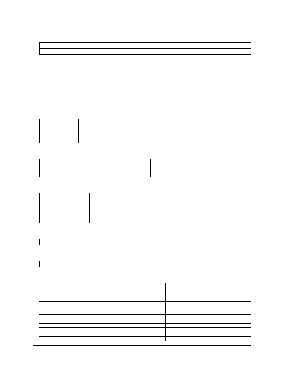
USB connection
Captive pigtail cable
USB Type A connector
Length
2 meters
Read/write benchmark timing
The following benchmarks are provided for reference only and were obtained with a single Switch & Sense 8
on a 500 MHz Pentium III running Windows 98 Second Edition. Performance figures can vary based on system
configuration.
Read timing reflects the total time to execute one read operation using the input functions provided in the
interface DLL. Write timing reflects the total time to execute one write operation using the output functions
provided in the interface DLL. The "write time" specified in the table below is the time to assert the relay
control line from the software interface.
Write timing
Throughput
20 mS typical
Relay set
10 mS (write time) + 10 mS (operate time) = 20 mS
Relay clear
10 mS (write time) + 5 mS (release time) = 15 mS
Read timing
Throughput
20 mS typical
Environmental
Operating temperature range
0 to 70 °C
Storage temperature range
-40 to 100 °C
Humidity
0 to 95% non-condensing
Mechanical
Card dimensions
165 mm long x 150 mm wide x 20 mm high, 6.5 in. long x 5.9 in. wide x 0.8 in. high
Case dimensions
185 mm long x 160 mm wide x 46 mm high, 7.3 in. long x 6.3 in. wide x 1.8 in. high
Case material
20 gage steel
Weight of complete unit
2.1 lbs.
Weight of card alone
0.6 lbs.
Screw terminal
Wire sizes
12-20 AWG
Miscellaneous
Case strain relief rating
20 lbs.
Screw terminal pinouts
Pin
Signal Name
Pin
Signal name
IP0A
Input 0 terminal A
IP4A
Input 4 terminal A
IP0B
Input 0 terminal B
IP4B
Input 4 terminal B
IP1A
Input 1 terminal A
IP5A
Input 5 terminal A
IP1B
Input 1 terminal B
IP5B
Input 5 terminal B
IP2A
Input 2 terminal A
IP6A
Input 6 terminal A
IP2B
Input 2 terminal B
IP6B
Input 6 terminal B
IP3A
Input 3 terminal A
IP7A
Input 7 terminal A
IP3B
Input 3 terminal B
IP7B
Input 7 terminal B
0-NO
Relay 0 Normally Open contact
4-NO
Relay 4 Normally Open contact
0-C
Relay 0 Common contact
4-C
Relay 4 Common contact
0-NC
Relay 0 Normally Closed contact
4-NC
Relay 4 Normally Closed contact