External power led, Status led, Usb connector – Measurement Computing SWITCH User Manual
Page 21: Internal components, Screw terminals and relays
Switch & Sense 8 User's Guide Template
Functional Details
21
External power LED
The LED labeled
EXTERNAL POWER
lights up when the Switch & Sense 8 is connected to an external power
source. It uses up to 5 mA of current and cannot be disabled.
Status LED
The LED labeled
STATUS
indicates the communication status of the Switch & Sense 8. It uses up to 5 mA of
current and cannot be disabled. The table below explains the function of the Switch & Sense 8 status LED.
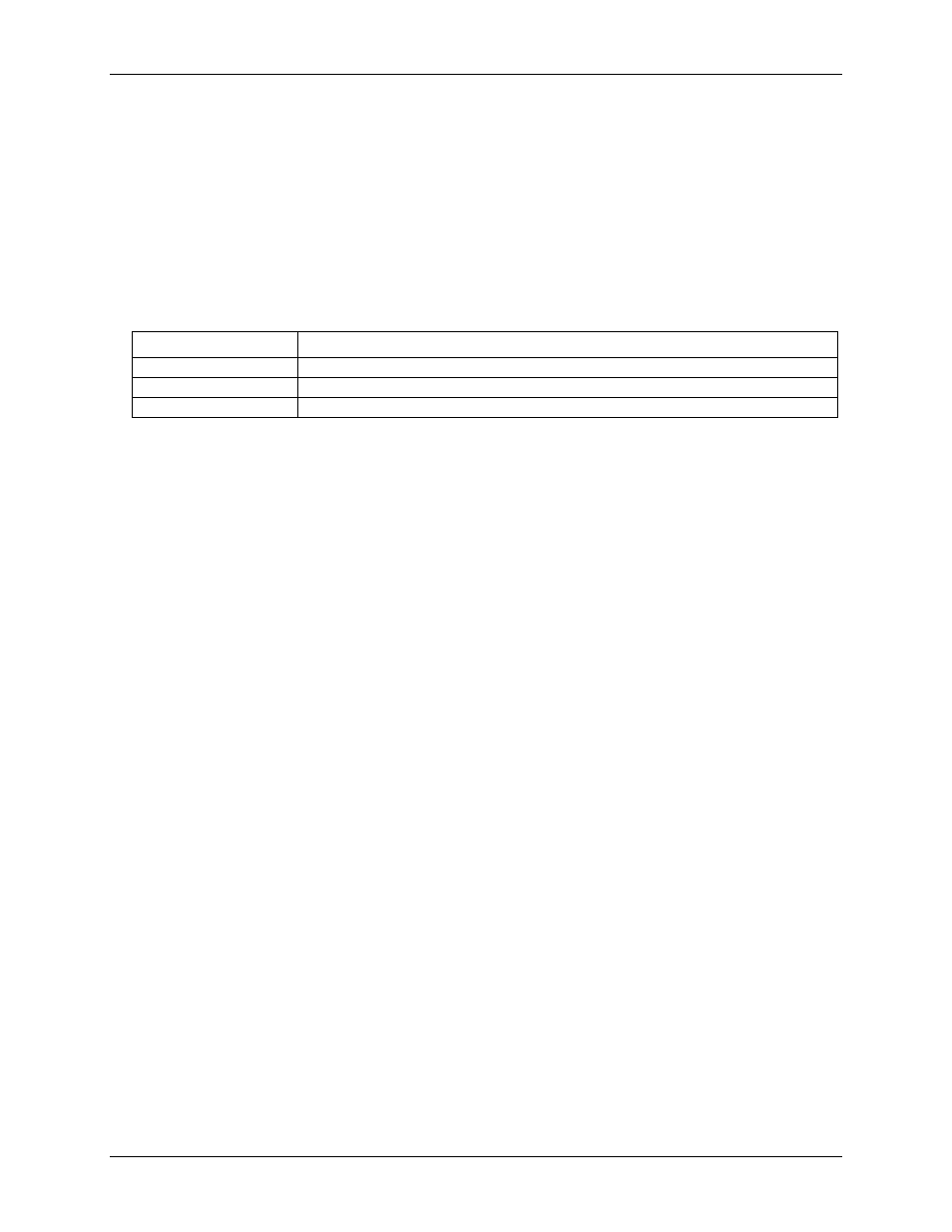
Status LED illumination
LED Illumination
Indication
Steady green
The Switch & Sense 8 is connected to a computer or external USB hub.
Blinks continuously
Data is being transferred.
Blinks three times
Initial communication is established between the Switch & Sense 8 and the computer.
USB connector
The USB connector is on the back of the Switch & Sense 8 housing. This connector provides +5 V power and
communication.
Internal components
Screw terminals and relays
The Switch & Sense 8 has four rows of screw terminals—two outer rows containing 12 terminals each, and two
inner rows containing eight terminals.
The outer rows of terminals connect to the eight relays available from the Switch & Sense 8.
The inner rows connect to the differential isolated digital inputs. No additional modules are required to
terminate any of the input or output signals.