Form c relay output – Measurement Computing SWITCH User Manual
Page 23
Switch & Sense 8 User's Guide Template
Functional Details
23
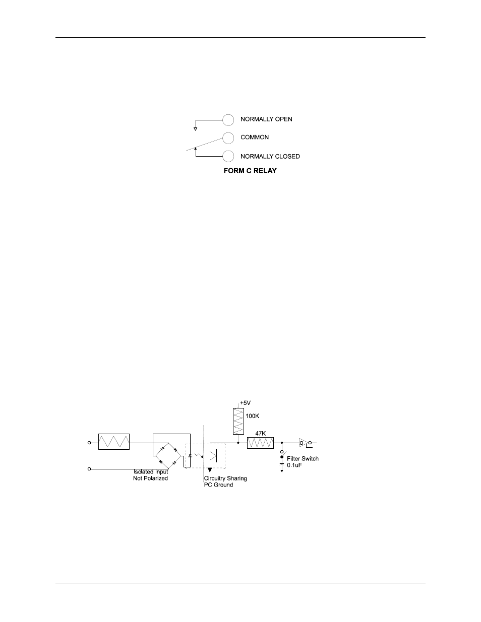
Form C relay output
A schematic for form C relay contacts is shown in Figure 4. The form C relay has a C, NO, and NC contact.
When a (0) is written to the output bit, the C and NC are in contact.
When a (1) is written to the output bit, the C and NO are in contact.
Figure 4. Form C SPDT relay
Differential isolated digital input terminals (IP0A to IP7B)
Connect up to eight isolated digital input lines using the following screw terminals pairs:
IP0A and IP0B
IP1A and IP1B
IP2A and IP2B
IP3A and IP3B
IP4A and IP4B
IP5A and IP5B
IP6A and IP6B
IP7A and IP7B
A schematic of a single channel is shown in Figure 5. Each signal is applied to a bridge rectifier so that the
input is not polarity-sensitive. It can be driven by either AC (50 - 1000 Hz) or DC voltage.
The eight optically isolated (500 V) inputs can be read back as a single byte. Each input has a software-
controlled filter with a time constant of 5 ms (200 Hz). The filter is required for AC inputs, and recommended
for almost all DC inputs. Unless you have a good reason to turn off a filter, we recommend that you enable it.
Refer to "Configuring isolated input filters" on page 19 to learn how to enable and disable the input filters.
Figure 5. Switch & Sense 8 single –channel configuration
1.6 K