3 system grounds and isolation, 4 determine your ground type – Measurement Computing CIO-DAS16Jr/16 User Manual
Page 9
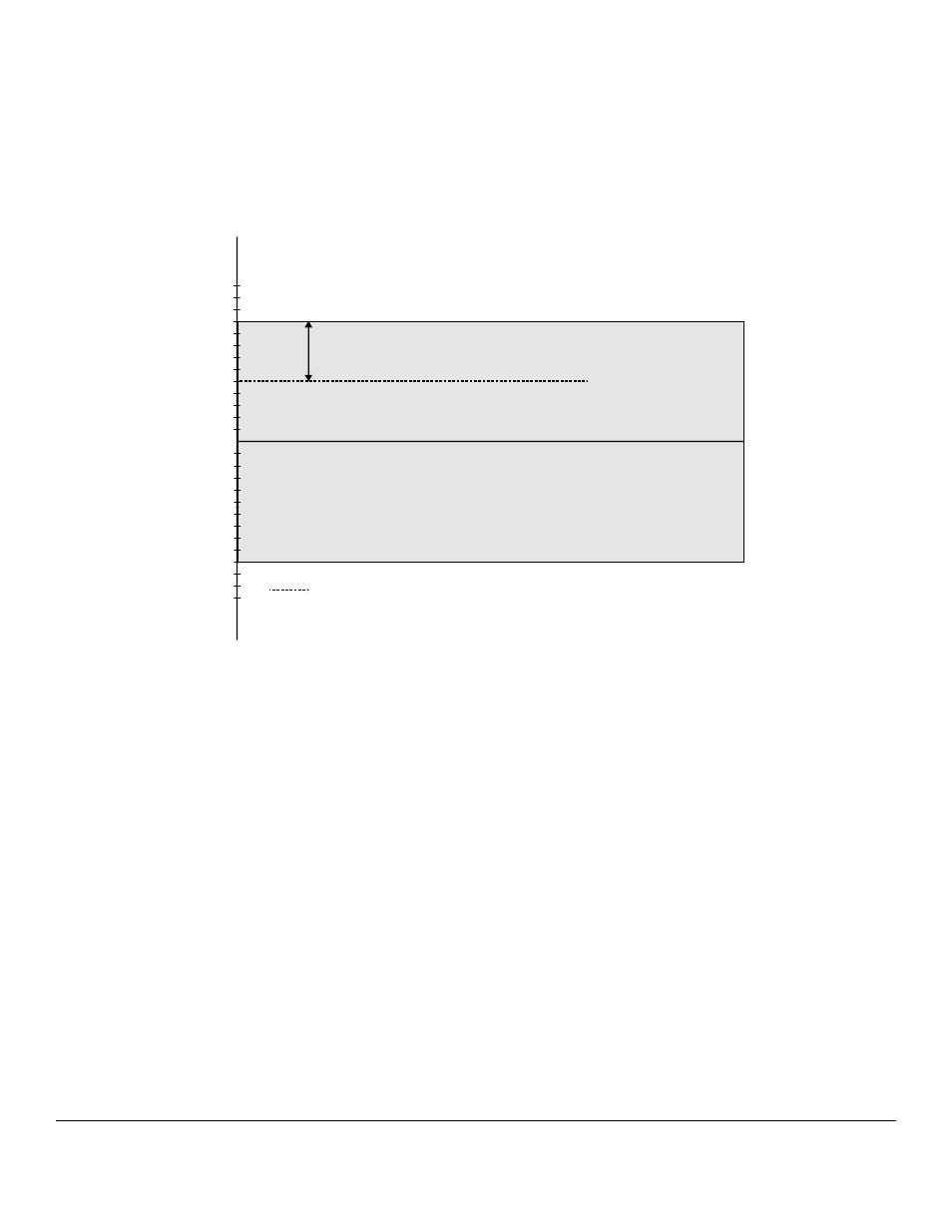
Before describing grounding and isolation, it is important to understand the concepts of common mode, and common
mode range. Common mode voltage is depicted in the diagram above as Vcm. Though differential inputs measure the
voltage between two signals, without (almost) respect to the either signal’s voltages relative to ground, there is a limit to
how far away from ground either signal can go. Though the CIO-DAS16JR/16 has differential inputs, it will not measure
the difference between 100V and 101V as 1 Volt (in fact the 100V would destroy the board!). This limitation or common
mode range is depicted graphically in the following diagram. The CIO-DAS16JR/16 common mode range is +/- 10 Volts.
Even in differential mode, no input signal can be measured if it is more than 10V from the board’s low level ground
(LLGND).
Figure 2-4. Common Mode Range Diagram
2.2.3 System Grounds and Isolation
There are three conditions possible when connecting the signal source to the board.
1
The board and the signal source may have the same (or common) ground. This signal source can be connected
directly to the board.
2
The board and the signal source may have an offset voltage between their grounds (AC and/or DC). This offset it
commonly referred to a common mode voltage. Depending on the magnitude of this voltage, it may or may not be
possible to connect the board directly to your signal source. We will describe this topic further in a later section.
3
The board and the signal source may already have isolated grounds. This signal source can be connected directly to
the board.
2.2.4 Determine Your Ground Type
Perform the following test: Using a battery powered voltmeter
1
, measure the voltage between the ground signal at your
signal source and ground at your PC. Measure both the AC and DC Voltages.
5
1
If you do not have a voltmeter, skip the test and read the following three sections. You may be able to identify your system type from the descriptions provided.
+ 1V
-13V
+ 2V
-12V
+ 3V
-11V
+ 4V
-10V
+ 5V
-9V
+ 6V
-8V
+ 7V
-7V
+ 8V
-6V
+ 9V
-5V
+1 0V
-4V
+11V
-3V
+1 2V
-2V
+1 3V
-1V
G ra y are a re p re se nts com m o n m o d e ra ng e
B o th V + an d V - m u st a lw a y s re m a in w ith in
th e c om m o n m o d e ra n ge re la tive to L L G n d
V cm (C o m m o n M o d e Vo ltag e ) = + 5 Volts
V cm
W ith V cm = + 5 V D C ,
+ V s m u st b e le ss th a n + 5 V, o r th e co m m o n m o d e ran g e w ill b e e xce e d e d (> + 1 0V )