Measurement Computing CIO-DAS16Jr/16 User Manual
Page 5
1 INSTALLATION
1.1 SOFTWARE
Before installing the board, install and run InstaCal. This package is the installation, calibration and test utility included
with your board. InstaCal will guide you through switch and jumper settings for your board. Detailed information
regarding these settings can be found below. Refer to the Software Installation manual for InstaCal installation
instructions.
The CIO-DAS16Jr/16 has one bank of base address-select switches and two single-function switches which must be set
before installing the board in your computer.
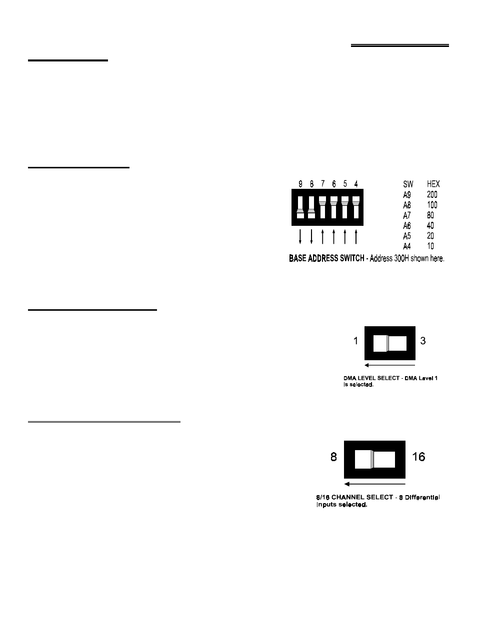
1.2 BASE ADDRESS
Unless there is already a board in your system that uses address 300
hex (768 decimal), leave the switches as they were set at the factory.
In the example shown in Figure 1-1, the board is set for base address
300h (768 decimal).
Figure 1-1 Base Address Switches
1.3 DMA LEVEL SELECT
The board is shipped with the DMA level switch set to DMA level 1. Unless you
have another board in your system using DMA level 1, leave the DMA level switch in
the level 1 position (Figure 1-2).
Some network boards use DMA and so do some IEEE-488 interface boards. If you
suspect a conflict with another board in the system, change the switch to level 3.
Figure 1-2. DMA Level Select Switch
1.4 8 or 16 CHANNEL SELECT
The analog inputs of the CIO-DAS16Jr/16 can be configured as 8 differential
or 16 single-ended. Using differential inputs allows up to 10 volts of common
mode (ground loop) rejection.
The CIO-DAS16Jr/16 comes from the factory configured for eight differential
inputs. Set it for the number of inputs (and type) you require (Figure 1-3).
Figure 1-3. Channel Number Select Switch
1