Measurement Computing CIO-DAS16Jr/16 User Manual
Page 8
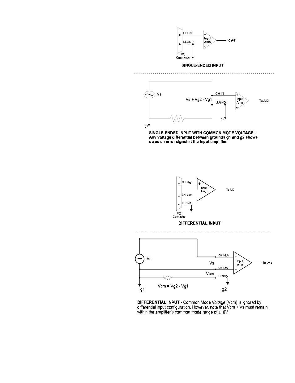
2.2.1 Single-Ended Inputs
In a single-ended input circuit, the voltage
between the input signal terminal and ground is
amplified. In this mode, the CIO-DAS16JR/16
amplifies the voltage between the selected input
channel CH IN and LLGND. The single-ended
input configuration requires only one physical
connection (wire) per channel and allows the
CIO-DAS16JR/16 to monitor more channels
than the (2-wire) differential configuration using
the same connector and on-board multiplexer
(not shown). However, since the circuit is
measuring the input voltage relative to its own
low level ground, single-ended inputs are more
susceptible to both EMI (Electro Magnetic
Interference) and any ground noise at the signal
source. Figure 2-2 shows the single-ended input
configuration.
Figure 2-2. Single-Ended Input Theory
2.2.2 Differential Inputs
In differential input circuits, the voltage between
two distinct input signals is amplified. Within a
certain range (referred to as the common mode
range), the measurement is almost independent of
signal source to CIO-DAS16JR/16 ground
variations. A differential input is also much more
immune to EMI than a single-ended one. Most EMI
noise induced in one lead is also induced in the
other, the input only measures the difference
between the two leads, and the EMI common to
both is ignored. This effect is a major reason there
is twisted pair wire as the twisting assures that both
wires are subject to virtually identical external
influence. Figure 2-3 shows a theoretical
differential input configuration. Note: Multiplexing
is not shown for simplification.
Figure 2-3. Differential Input Theory
4