10 analog input, 11 digital input & output, 12 output – Measurement Computing CIO-DAS16Jr/16 User Manual
Page 21: 13 input
The three 8254 counter/timer data registers may be written to and read from. Because each counter will count as high as
65,535, it is clear that loading or reading the counter data must be a multi-step process. Refer to the 8254 data sheet
at
http://www.measurementcomputing.com/PDFmanuals/82C54.pdf for details regarding the programming of the 8254
counter / timer.
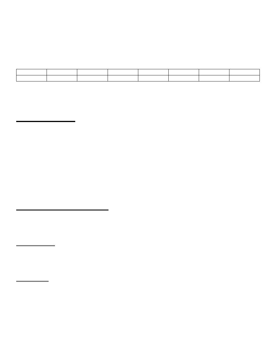
82C54 COUNTER CONTROL
BASE ADDRESS + 15
D1
D2
D3
D4
D5
D6
D7
D8
0
1
2
3
4
5
6
7
WRITE ONLY
This register controls the operation and loading/reading of the counters. Refer to the 8254 data sheet
at
http://www.measurementcomputing.com/PDFmanuals/82C54.pdf for details regarding the programming of the 8254
counter / timer.
3.10 ANALOG INPUT
Analog signals connected to P1, the 37D connector which protrudes from the expansion slot of the PC, are first fed into
the two HI-0508 analog multiplexers. A multiplexer's (MUX) function is to select one of several (8) inputs and connect
that input to the MUX output. MUX U5 connects CH0-CH7 high inputs. MUX U9 connects CH0-CH7 Low input
(differential input mode) or CH8-CH15 High inputs (single-ended mode) depending on the state of the channel
configuration switch located at the upper right of the board and marked 8/16.
From the output of the MUX, the analog signal is fed into a programmable differential amplifier.
The A/D converter chip has an integral sample & hold circuit, greatly simplifying design and improving signal integrity.
The A/D converter is capable of sampling rates to 100 kHz but the DMA transfer circuitry of the personal computer's
8-bit bus may limit the transfer rate to less than the maximum A/D rate. Therefore, the maximum sampling rate of the
CIO-DAS16Jr/16 is dependent on the computer.
3.11 DIGITAL INPUT & OUTPUT
There are four bits of output-only and four bits of input-only on the CIO-DAS16Jr/16 analog connector. From the
original DAS-16 design, these were the only eight bits of digital I/O.
3.12 OUTPUT
The output bits are part of chip U20, a 74LS197 output buffer. The other half of the chip is used for on-board control. If
the digital output lines are blown by overload or high voltage connection, you can replace this chip.
3.13 INPUT
The input bits are part of chip U23, a 74LS244 buffer. The other half of this chip is used for on board functions. This
chip is socketed.
17