Measurement Computing CIO-DAS16Jr/16 User Manual
Page 7
2 SIGNAL CONNECTIONS
2.1 CONNECTOR DIAGRAM
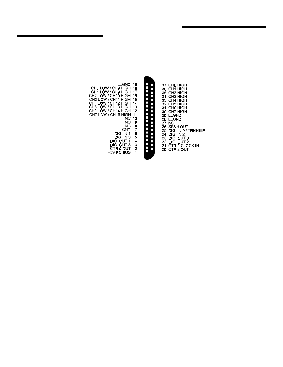
The CIO-DAS16Jr/16 analog connector is a male 37-pin, D-type connector accessible from the rear of the PC through the
expansion backplate. The signals available are identical to the DAS-16, with the exception of pins 8, 9, 10 and 27 (D/A
signals on the DAS-16, no-connect on the CIO-DAS16Jr/16). Another signal, SS&H OUT, can be accessed at pin 26.
Figure 2-1. Connector Pin-Out
The connector (Figure 2-1) accepts female 37-pin D-type connectors, such as those on the C73FF-2, a 2-foot cable with
connectors.
If frequent changes to signal connections or signal conditioning is required, please refer to the information on the
CIO-MINI37 or CIO-TERMINAL screw terminal boards.
For signal conditioning and channel expansion, refer to the information on CIO-EXP32, a 32 channel analog
multiplexer/amplifier; CIO-SSH16, a 16 channel simultaneous sample & hold board or the ISO-RACK16 5B module
interface rack.
2.2 ANALOG INPUTS
Making reliable, trouble-free analog signal connections can be a challenge when using a data acquisition board. The best
method for inputting analog inputs may not be obvious. While a complete coverage of this topic is beyond the scope of
this manual, the following section provides simple explanations and helpful hints. When finished, you should have a
basic understanding of single-ended versus differential inputs and the concepts of system grounding and isolation.
The CIO-DAS16Jr/16 provides either eight differential or 16 single-ended input channels. Descriptions of single-ended
and differential inputs follow.
3
/ CTR0 GATE