7 pacer clock control register – Measurement Computing CIO-DAS16Jr/16 User Manual
Page 19
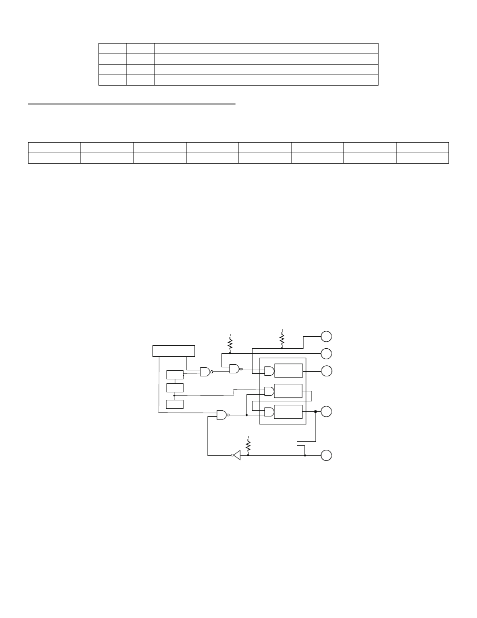
Table 3-3. A/D Conversion Source Coding
Start on Pacer Clock Pulse (CTR 2 OUT, no external access)
1
1
Start on rising TRIGGER (Digital input 0, Pin 25)
0
1
Software triggered A/D only
X
0
TS0
TS1
3.7 PACER CLOCK CONTROL REGISTER
BASE ADDRESS + 10
TRIG0
CTR0
X
X
X
X
X
X
0
1
2
3
4
5
6
7
Write only
CTR0 = 1. When CTR0 = 1, an on-board 100 kHz lock signal is ANDed with the COUNTER 0 CLOCK INPUT (pin
21). A high on pin 21 will allow pulses from the on-board source into the 82C54 Counter 0 input.
CTR0 = 0. When CTR0 = 0, the input to 82C54 Counter 0 is entirely dependent on pulses at pin 21, COUNTER 0
CLOCK INPUT.
TRIG0 = 1. When TRIG0 = 1, the TRIGGER input at pin 25 is ANDed with TRIG0 which must therefore be high for
the pulses from the on-board pacer clock (82C54) to start A/D conversions. The input at pin 25 is pulled up and will
always be high unless pulled low externally.
TRIG0 = 0. When TRIG0 = 0, the GATEs of counter 1 & 2 are held high, preventing gating of the pacer clock from
pin 25. Reviewing Figure 3-1 may help in understanding the functions of these registers.
Figure 3-1. Pacer Control Logic
15
10 MHz
2
COUNTER 0
20
COUNTER 2
COUNTER 1
A/D PACER
25
24
+5V
10K
21
+5V
10K
CONTROL REGISTER
BASE + 10
TR IG
CTR0
GATE
GATE
GATE
OUT
OUT
OUT
+5V
10K
CIO-DAS16 8254 PACER CLOCK & CONTROL
CTR 2 OUT
CTR 0 OUT
TRIGGER
GATE 0
CTR 0 IN
10 MHz
2
COUNTER 0
20
COUNTER 2
COUNTER 1
A/D PACER
25
24
+5V
10K
21
+5V
10K
CONTROL REGISTER
BASE + 10
TR IG
CTR0
GATE
GATE
GATE
OUT
OUT
OUT
+5V
10K
CIO-DAS16 8254 PACER CLOCK & CONTROL
CTR 2 OUT
CTR 0 OUT
TRIGGER
GATE 0
CTR 0 IN
1/10
1/10
0