3 common mode voltage < +/-10v/single-ended inputs, 4 common mode voltage < +/-10v/differential inputs, 5 common mode voltage > +/-10v – Measurement Computing CIO-DAS16Jr/16 User Manual
Page 13: Common mode voltage < +/-10v/single-ended inputs, A /d b oa rd, A /d b o ard
2.3.3 Common Mode Voltage < +/-10V/Single-Ended Inputs
This is not a recommended configuration. In fact, the phrase common mode has no meaning in a single-ended system and
this case would be better described as a system with offset grounds. Anyway, you are welcome to try this configuration,
no system damage should occur and depending on the overall accuracy you require, you may receive acceptable results.
2.3.4 Common Mode Voltage < +/-10V/Differential Inputs
Systems with varying ground potentials should always be monitored in the differential mode. Care is required to assure
that the sum of the input signal and the ground differential (referred to as the common mode voltage) does not exceed the
common mode range of the A/D board (+/-10V on the CIO-DAS16JR/16). Figure 2-7 below show recommended
connections in this configuration.
Figure 2-7
.
Common Mode Voltage < +/-10V/Single-Ended Inputs
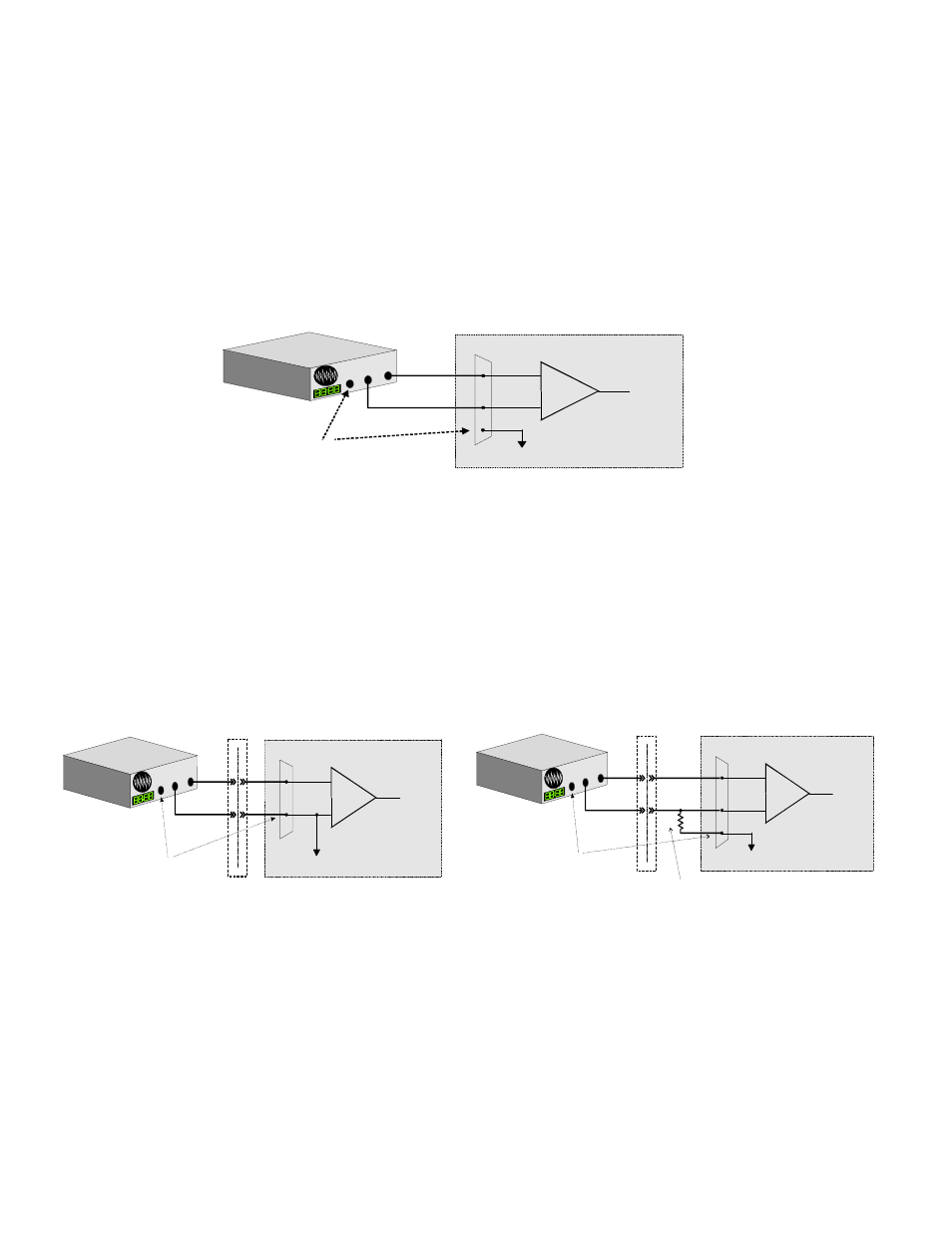
2.3.5 Common Mode Voltage > +/-10V
The CIO-DAS16JR/16 will not directly monitor signals with common mode voltages greater than +/-10V. You will either
need to alter the system ground configuration to reduce the overall common mode voltage, or add isolated signal
conditioning between the source and your board (Figure 2-8).
Figure 2-8. Common Mode Voltage > +/-10V - Serial/Differential Inputs
9
+
-
In p ut
A m p
To A /D
A /D B o a rd
I/O
C o n n ec to r
L L G N D
C H H ig h
C H L o w
S ig n
al S o
u rce
w i
th C o
m m o
n
M o d
e Vo
ltage
S ig n a l s o u rc e a n d A /D b o a rd
w ith c o m m o n m o d e v o lta g e
c o n n e c te d to a d iffe re n tia l in p u t.
G N D
T he vo ltag e d ifferen tia l
b etw ee n the s e groun d s,
a dde d to the m a x im u m
in p ut s ig na l m ust s ta y
w ithin +/-10 V
System w ith a Large C om m on M ode Voltag e,
C onne cte d to a D ifferential Input
L
arge c
om m on
m ode v
oltage
b
etw ee
n sign
al
s
ource &
A/D b
oard
G N D
Iso latio n
B arrie r
W hen the voltage difference
between signal source and
A/D board ground is large
enough so the A/D board’s
com m on m ode range is
exceeded, isolated signal
conditioning m ust be added.
+
-
Inp ut
A m p
To A /D
A /D B oa rd
I/O
C onnector
LL GN D
CH H igh
CH Low
10 K
10K is a recom m ended valu e. You m ay short LL GN D to C H Low
instead, but this w ill reduce your system ’s noise im m unity.
System w ith a Large C omm on M ode Voltage,
Connected to a S ingle-Ended Input
I/O
C o nn ector
+
-
Inp ut
A m p
To A /D
LL G N D
C H IN
A /D B o ard
L
arge c
om m o
n
mo
de vol
tage
betw e
en sig
nal
so
urce &
A /D b
oard
G N D
Isolation
Barrier
W hen the voltage difference
betw een signal source and
A/D board ground is large
enough so the A/D board’s
com m on m ode range is
exceeded, isolated signal
conditioning m ust be added.