8 analog input range register, 9 pacer clock data & control registers – Measurement Computing CIO-DAS16Jr/16 User Manual
Page 20
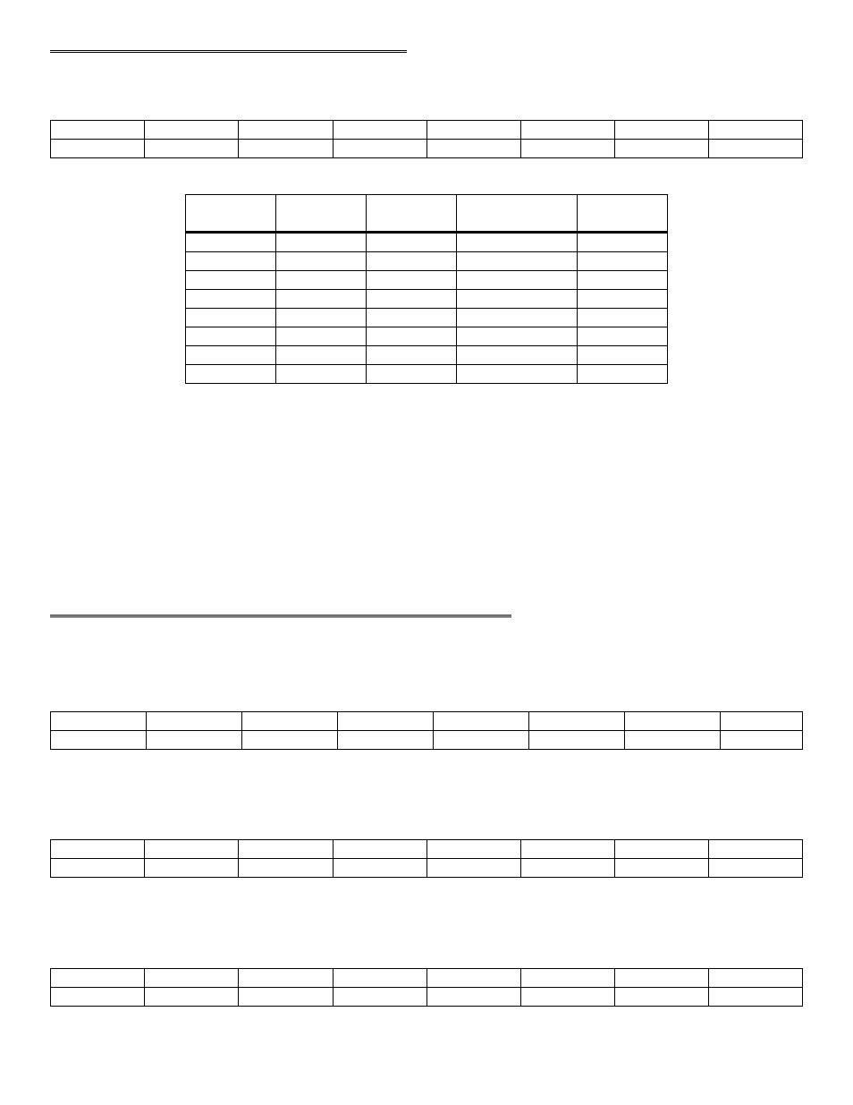
3.8 ANALOG INPUT RANGE REGISTER
BASE ADDRESS + 11
G0
G1
Uni/Bip
X
X
X
X
X
0
1
2
3
4
5
6
7
Table 3-4. Range Coding
7
0 to 1.25V
1
1
1
6
0 to 2.5V
0
1
1
5
0 to 5V
1
0
1
4
0 to 10V
0
0
1
3
±1.25V
1
1
0
2
±2.5V
0
1
0
1
±5V
1
0
0
0
±10V
0
0
0
DECIMAL
INPUT
RANGE
G0
G1
UNI/BIP
READ or WRITE
A write to this register sets the analog input range for all 8/16 analog inputs. The lower three bits set the analog input
range (Table 3-4). The upper five bits are not used.
To set the analog input range of the CIO-DAS16Jr/16 programmatically, write the correct input range code to the base
address + 11. For example, from BASIC:
If the board's base address is 300h (768 decimal), then the gain register is at 768 + 11 = 779
OUT 779, 5
'Set analog output range to 0 to 5V
The decimal range codes are in the far right column above.
3.9 PACER CLOCK DATA & CONTROL REGISTERS
8254 COUNTER 0 DATA
BASE ADDRESS + 12
D1
D2
D3
D4
D5
D6
D7
D8
0
1
2
3
4
5
6
7
8254 COUNTER 1 DATA
BASE ADDRESS + 13
D1
D2
D3
D4
D5
D6
D7
D8
0
1
2
3
4
5
6
7
8254 COUNTER 2 DATA
BASE ADDRESS + 14
D1
D2
D3
D4
D5
D6
D7
D8
0
1
2
3
4
5
6
7
16