Multi-channel trigger – Measurement Computing WaveBook rev.4.0 User Manual
Page 56
4-10 WaveBook Operation Reference
06-08-01
WaveBook User’s Manual
•
Without SSH, the trigger threshold is settable from -5.0 to +9.996 volts with 12-bit
(WaveBook/512) resolution, regardless of any channel's gain settings. This gives better than
1% resolution at even the smallest input ranges (such as 0-1 or ±0.5 volts).
•
With SSH, the single-channel (Channel 1 analog) signal is first amplified by the SSH
programmable gain amplifier before being compared with the programmable voltage. This
allows precise trigger-level adjustment, even at high gain. The analog-trigger comparator
threshold-voltage range and resolution (with SSH) are shown in the following table.
SSH Input Range
Trigger Threshold Range
WaveBook/512
12-Bit Resolution (mV)
WaveBook/516
16-Bit Resolution (mV)
0-10 or ±5
-5.0 to 9.996
3.66
0.299
0-5 or ±2.5
-2.5 to 4.998
1.83
0.114
0-2 or ±1
-1.0 to 1.999
0.732
0.0458
0-1 or ±0.5
-0.5 to 0.9996
0.366
0.0229
0-0.5 or ±0.25
-0.25 to 0.4998
0.183
0.0114
0-0.2 or ±0.1
-0.10 to 0.1999
0.0732
0.00458
0-0.1 or ±0.05
-0.05 to 0.09996
0.0366
0.00229
Hysteresis
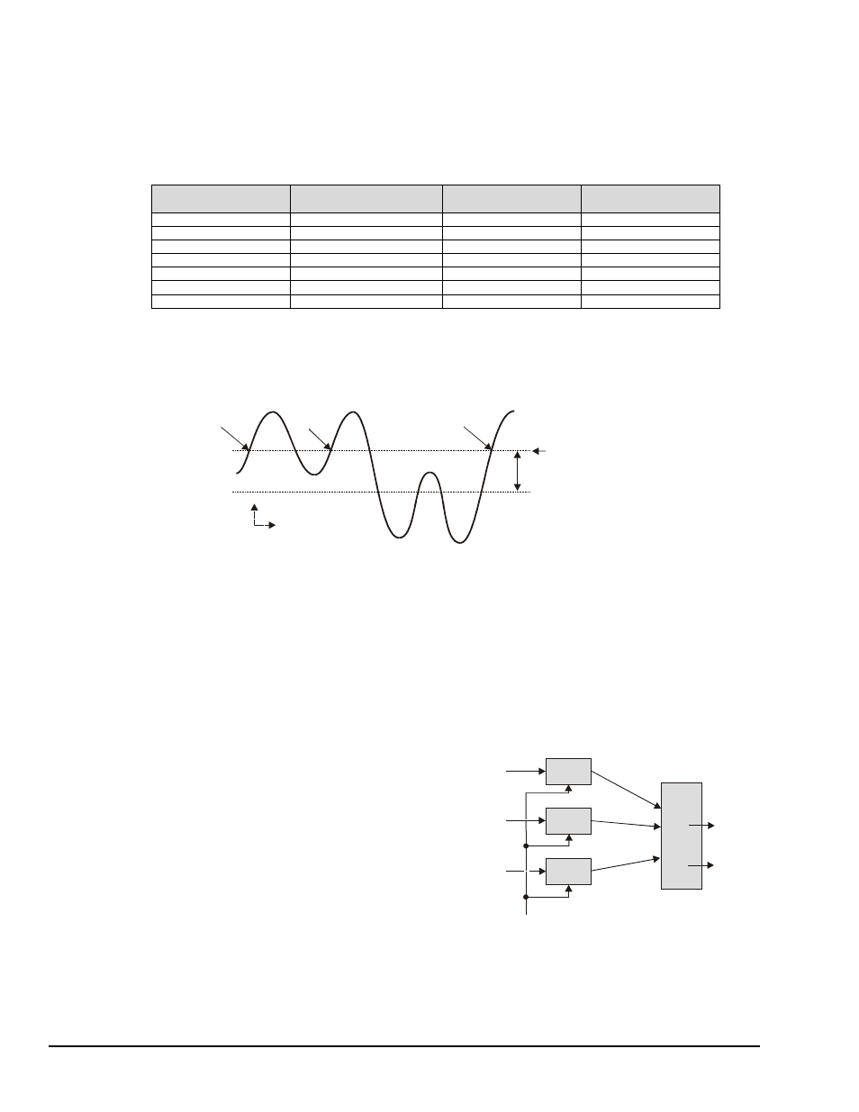
The analog trigger circuit has hysteresis that reduces the occurrence of retriggering due to input noise.
The hysteresis level without SSH is 25 mV; the hysteresis with SSH is 1/600 of the comparator range. The
next figure shows the hysteresis effect for a rising-edge trigger.
Trigg e r
Trigg e r
N o
Trigg e r
Trigg e r L ev el
H ys te re sis R a ng e
H y s te re s is E ffe c t o n a R isin g -E d g e Trig g e r
A m plitud e
Tim e
A trigger will occur when the analog input rises above the trigger level—but only after the input level has
been below the hysteresis range. If the level momentarily drops just below the trigger level (perhaps due to
noise) and then rises above it again, no extra triggers will be generated—the signal did not drop below the
hysteresis range. After the level drops below hysteresis, it can then again produce a trigger by rising above
the trigger level.
Multi-Channel Trigger
When the small hardware-limited latencies of the digital (TTL) and single-channel (Channel 1 analog)
triggers are not required, the DSP chip may be used to examine the samples from one or more channels and
to decide if they constitute a pre-defined trigger condition.
The DSP can sample up to 72 input channels and
examine each one to determine if it meets programmed
levels for a valid trigger. This multi-channel triggering
is a two-step process:
1.
The DSP examines each of its specified input
signals to determine trigger validity.
2.
After all of the channels have been examined, the
DSP logically combines the individual triggers to
generate the actual trigger. The DSP may be
programmed to generate a trigger if any individual
trigger is valid (OR) or if all triggers are valid
(AND). See figure.
Trigger
Detector
Trigger
Detector
Analog
Input
Signals
Invalid Trigger
Valid Trigger
Valid Trigger
Re-Arm Command
From Control Circuits
No Trigger
AND
(all)
Trigger
OR
(any)
Trigger
Logic
Trigger
Detector
Multi-Channel Trigger Detection
Trigger validity in a multi-channel environment is determined by the logical relationship among three
elements (slope, duration, and initialization) as discussed in the next section.