Wavebook/516, basic operation, Wavebook/516, basic operation …… 4-4 – Measurement Computing WaveBook rev.4.0 User Manual
Page 50
4-4 WaveBook Operation Reference
06-08-01
WaveBook User’s Manual
WaveBook/516, Basic Operation
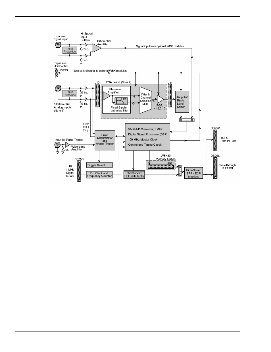
WaveBook/516 Block Diagram
Note 1:
Each channel has input protection and connects to J10 via its own BNC connector. Channel 1 is the only channel that
connects to the Pulse Discriminator and Analog Trigger.
Note 2:
An optional WBK11, WBK12, or WBK13 series board can be used in place of WaveBook/516’s PGA board. For
WaveBook/516, these boards are not “Plug-and-play.” They are only to be installed at the factory.
In regard to WaveBook/516, each of the 8 pairs of differential signals (one per BNC connector) is buffered
and applied to a differential amplifier. The output of each differential amplifier is applied to a 5 pole, low
pass filter. The filter and channel-selection multiplexer then switches the non-filtered and filtered signals to
a programmable gain amplifier (PGA). The amplified signal is level-shifted to locate the desired range
(within the A/D converter's fixed input range). Two offset settings are available, unipolar and bipolar.
Unipolar offset is used for sampling signals that are always positive. Bipolar offset is used for signals that
may be positive or negative. For example, when set for unipolar at a gain of ×5, the input span is 2 volts
and the amplified signal is offset so that input voltages from 0 to +2 volts can be digitized. When set for
bipolar operation, the offset is adjusted so that input voltages from -1.0 to +1.0 volts can be digitized.
The signal is switched over to the A/D converter and digitized to 16 bits in 1 µs. Note that the A/D
converter's input can be switched to the expansion signal input, allowing the device to read one of 64
possible expansion channels (supplied by up to eight WBK10 expansion chassis). The digital signal
processor (DSP) processes the digitized value and corrects the value for gain and offset errors. The DSP
places the corrected result into the FIFO data buffer that holds the samples until the PC reads the data. If the
sample is used for triggering, the DSP determines if a valid trigger event has occurred.