Measurement Computing WaveBook rev.4.0 User Manual
Page 49
WaveBook User’s Manual
06-08-01
WaveBook Operation Reference 4-3
For every sample, the DSP reads from a scan sequence table and accordingly programs the control-and-
timing circuit for the next sample. The circuit waits precisely until the start of the next sample and then
selects the: input channel, PGA gain, level-shifter offset, and A/D input source. It also conveys this
information to any attached expansion units and precisely controls the A/D conversion timing.
The EEPROM holds the calibration information needed for real-time sample correction.
The digital I/O port is read and written by the Digital Signal Processor to transfer bytes of digital data.
It may be used as a simple 8-bit input port or as a 32-address byte-wide I/O port.
The high-speed EPP/ECP interface circuit connects the WaveBook and any attached printer to the PC via
standard DB-25 connectors. When the WaveBook is active, the interface holds the printer in a stable state;
and when the WaveBook is inactive, the interface connects the PC to the printer.
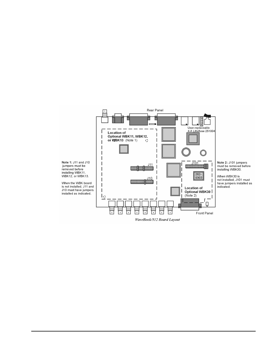
Pin-header J101 allows the addition of the WBK30 memory option. The WBK30 is detailed in the
WBK30 Document Module. Pin-headers J10 and J11 allow the addition of the optional WBK11, WBK12,
or WBK13. These cards can also be added toWBK10/10H/10A expansion modules.