Digital i/o connections…… 4-7, Digital i/o connections – Measurement Computing WaveBook rev.4.0 User Manual
Page 53
WaveBook User’s Manual
06-08-01
WaveBook Operation Reference 4-7
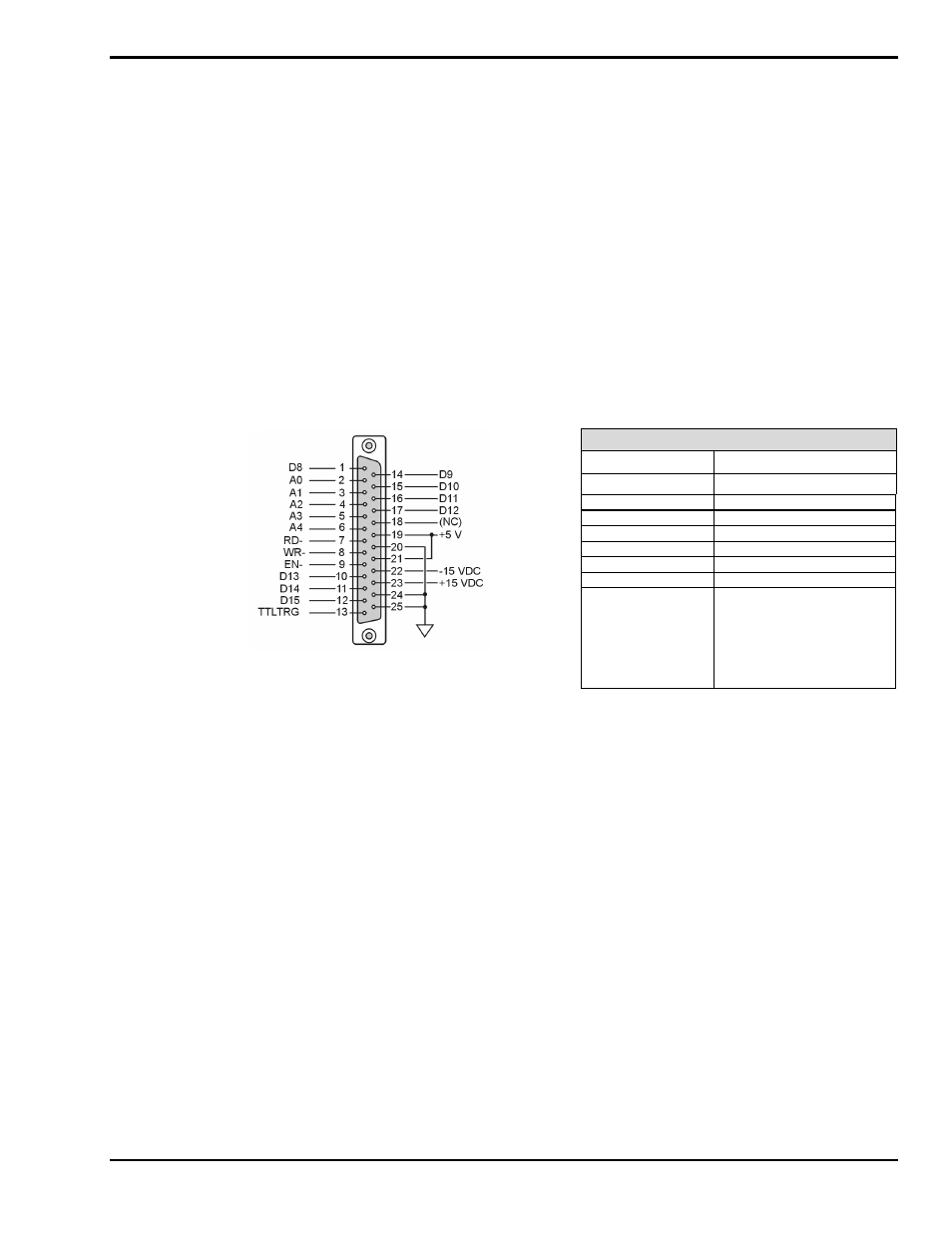
Digital I/O Connections
Digital I/O Connections for WaveBook/512 and WaveBook/512H
Note: The following pinout can be used for WaveBook/516, providing the unit is in the 8-bit mode (instead of 16-bit).
If using this pinout for WaveBook/516 (in 8-bit mode), pin 20 will be assigned to external clock input.
With the WaveBook/512 series, the following signals are present on the DB25F high-speed digital I/O
connector.
•
8 Digital I/O Lines (D8 – D15)
•
5 Address Lines (A0 –A4)
•
Active-low Digital I/O Enable output (EN-)
•
Active-low Digital I/O Write Strobe (WR-)
•
Active-low Digital I/O Read Strobe (RD-)
•
TTL Trigger Input (TTLTRG)
•
+15 V (pin 23), -15 V (pin 22), 50 mA max. (each)
•
two +5 V power (pins 19 and 21), 250 mA max. (total)
•
three Digital Grounds (pins 20, 24, and 25)
Digital I/O Connections, WaveBook/512
D8-D15
Digital I/O data lines
A0-A4
Digital I/O address lines
EN-
Active-low digital I/O enable
RD-
Active-low read strobe
WR-
Active-low write strobe
TTLTRG
TTL trigger input
+5 VDC
250 mA maximum
+15,-15 VDC
50 mA maximum (each)
WaveBook/512, DB25 Pinout
Digital Grounds
Pins 20, 24, and 25
To sample just 8 digital input signals, connect them directly to the digital I/O data lines. D15 is the most
significant bit, and D8 is the least. The address lines, the read and write strobes, and enable signal may all
be left disconnected.