Measurement Computing eZ-Balance rev.9.0 User Manual
Page 28
3-10 Windows, Buttons, and Menus
969391
eZ-Balance
Configuration Window . . . Input Channels Tab
Attribute
Comments
Coupling
AC or DC coupling can be set on an individual channel basis. Coupling is available for
analog channels (CH1 through CH8) and for compatible expansion channels [e.g., from a
WBK18]. AC Coupling can be set to a high pass filter value of 0.1 Hz or 1 Hz. The
value is selected in the Analyzer Tab. Note that when DC Coupling is selected the high
pass filter is bypassed.
When the Coupling function is not available to a channel, or not used by a channel, a
dash appears in that channel’s Coupling column.
mV/EU
This is the instrument’s input Sensitivity. Typical accelerometers have a sensitivity of
100 mV per g. Displacement probes have 200 mV per mil.
For Tach probes enter 1000 mV per Volt.
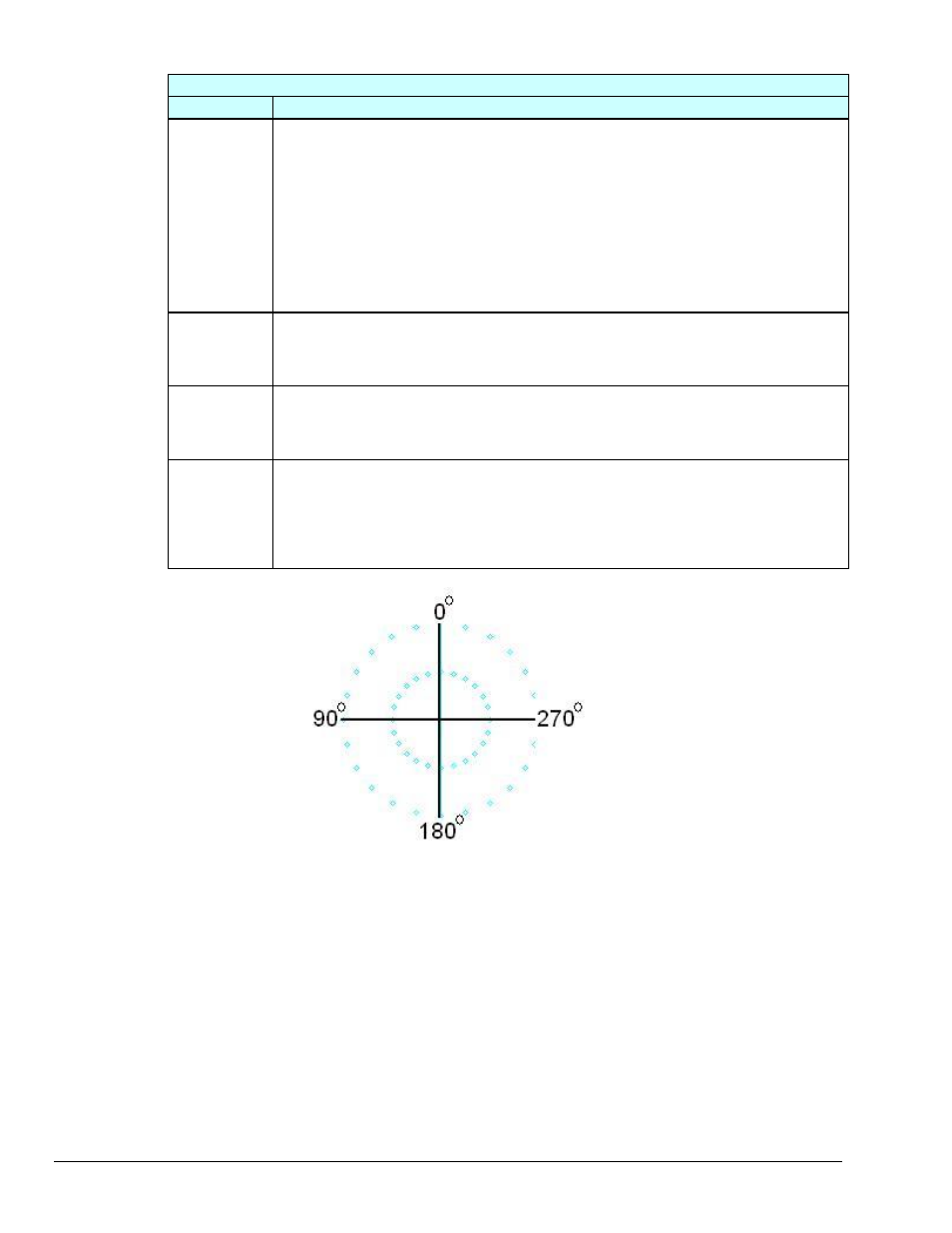
Angle
Angle refers to the physical angular location of a probe. Zero degrees is defined to be
TDC (+y-axis). The angle value is measured in the counterclockwise (CCW) direction.
Typically viewed from the driver end. Instrument angle is used for data display.
1xA Ref
1xP Ref
The 1x (first order) Amplitude and Phase values are used for
Runout Compensation on Bode or Polar displays. These values are commonly known as
Slow Roll Compensation values and should be collected during machine slow roll
conditions (i.e.: Speeds < 500 rpm). The values must be between the Maximum and
Minimum EU range.