Hpf cutoff, Source level, Bridge type – Measurement Computing WaveView User Manual
Page 18: Invert
WaveView, pg. 16
03-05-02
WaveView
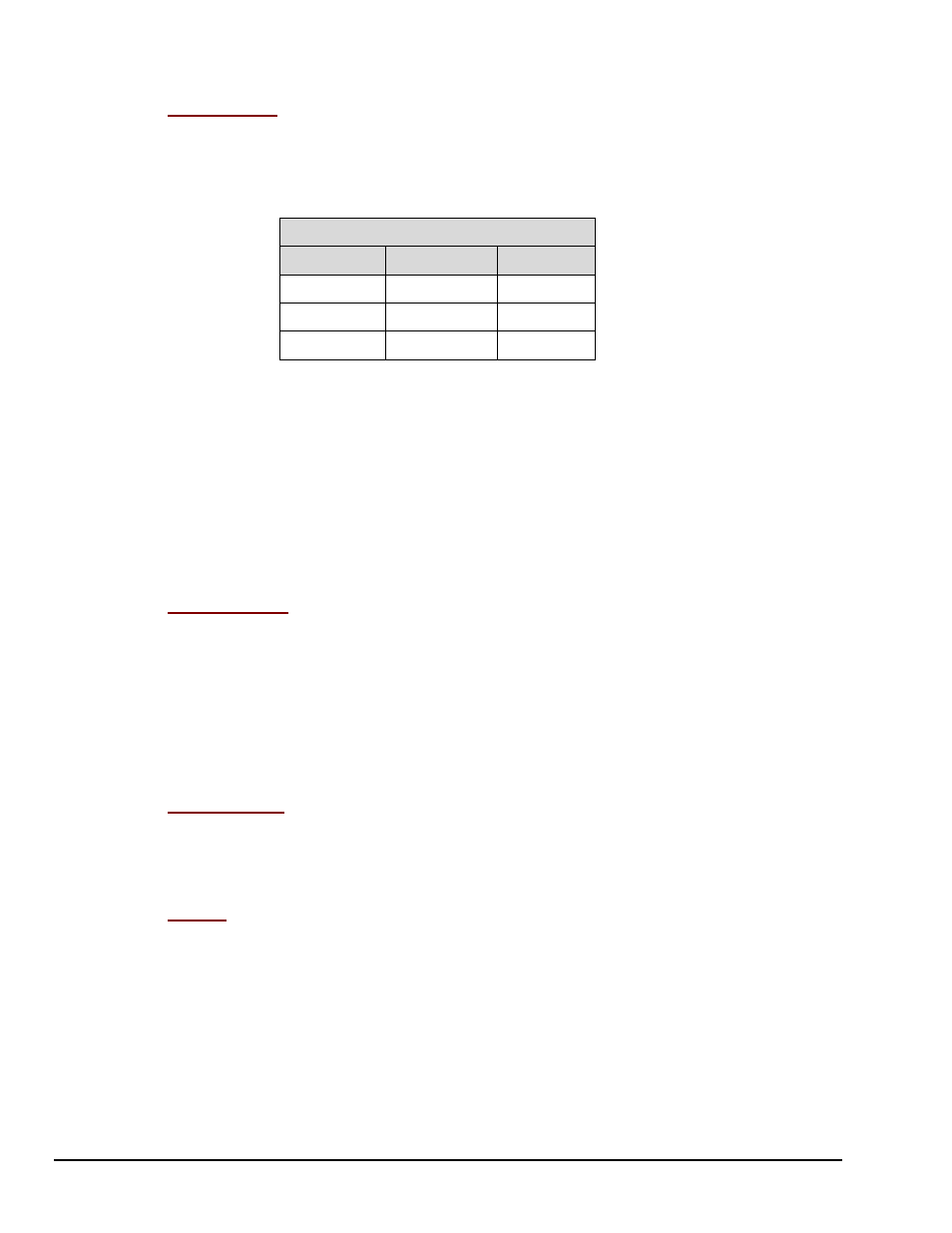
HPF Cutoff –
Applies to: WBK14, WBK16, and WBK17. This column allows you to set the high-
pass filter cut-off frequency for the selected channel(s), or in the case of the WBK17, to select AC or DC
coupling. When a spreadsheet cell is selected [in the HPF cutoff column], a selection box above the
spreadsheet will display the options available for configuring the filters. Double-clicking a cell in this
column will toggle the cut-off frequency status. A change in the high-pass filter cut-off frequency for one
channel will appropriately update other affected channels.
HPF Cutoff Options
WBK14
WBK16
WBK17
0.1 Hz
DC
Off
10 Hz
1 Hz
AC
--
--
DC
WBK17 users should note that each WBK17 channel has a programmable input-coupling feature. Input
coupling can be turned off, or be selected for AC or DC coupling. The inclusion [or exclusion] of DC
offsets is important when calculating the appropriate comparator threshold for the input waveform.
In regard to WBK17’s AC coupling option – select “AC” to reject unwanted DC offsets. In other words,
to prevent DC offsets from reaching the comparator. AC coupling works well when the input is constantly
changing. If the input stops for longer than one second, it will appear as DC and may cause the comparator
to switch on the decaying DC input.
In regard to WBK17’s DC coupling option – use “DC” coupling when both AC and DC components are
to be presented as input to the comparator DC coupling does not reject anything. If the input can have
periods of stability longer than one second, use DC coupling so the comparator does not switch on a
decaying DC input.
Source Level –
Applies to: WBK14 and WBK16. This column allows you to apply or remove the
source level for the selected channel(s). When selecting a cell or block of cells in this column, a selection
box above the spreadsheet may or may not appear, depending upon your particular hardware. If the
selection box appears, it will display the appropriate source level selections (such as “Off”, “2 mA”, or
“4 mA” for a WBK14 or an excitation voltage level for a WBK16) allowed by your hardware to configure a
source or block of sources. Double-clicking a cell in this column will toggle the source level status. A
change in the source level for one channel will appropriately update any other affected channels.
➪
WBK14 Note
– For WBK14, when using an ICP transducer, either 2 mA or 4 mA must be selected.
Set the current-source level to “Off” before measuring voltage.
Bridge Type
–
Applies to WBK16 Only. This column allows you to select the specific bridge
configuration for a strain gage or load cell sensor. When a cell is selected, a selection box above the
spreadsheet will display the appropriate bridge configuration selections (such as Full Bridge, Half-Bridge
and Quarter-Bridge). Double-clicking a cell in this column toggles the Bridge Type. Detailed information
is included in the WBK16 Document Module.
Invert –
Applies to: WBK16 Only. This column allows you to invert the signal level of a channel.
When a cell is selected, the selection box above the spreadsheet allows “Yes” or “No” options to determine
whether the channel is inverted. Double-clicking a cell in this column will toggle the invert status.