View, System – Measurement Computing WaveView User Manual
Page 12
WaveView, pg. 10
03-05-02
WaveView
View
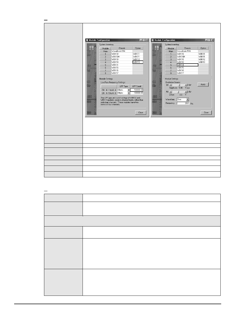
Module Configuration
Displays the current inventory of expansion modules that are in the WaveBook system. In
addition, the window provides a means of setting certain expansion module parameters,
i.e., LPF Type and LPF cutoff for WBK12 and WBK13 options and excitation source
amplitude and offset for WBK14. The following figure provides two examples.
Two Examples of the Module Configuration Display Window
The window can be accessed from the View pull-down menu or by using the
associated toolbar button (1).
Acquisition
Configuration
Opens the display window to allow selection of the number/speed of the scan and the
triggering method to start the scan.
Scope Window
Opens the display window to allow real-time viewing of the acquired data.
Direct to Disk
Window
Opens the display window to allow the writing of acquisition data to disk files.
View File Data
Starts the independent application to view file data.
Bar Graph Meters
Used to display one or more channels in bar graph format.
Analog Meters
Used to display one or more channels in analog meter format.
Digital Meters
Used to display one or more channels in digital meter format.
System
Select Device
Brings up a dialog box that lets you select a WaveBook device. It also provides access to
the Simulated Device, which is listed as an option.
Options
Brings up the WaveView System Options dialog box. From there, you can enable or disable
WaveView options. The options dialog box has three tabs: Performance, Memory
Module, and WBK17. The three tab selections are discussed, following this table.
Note: The following System selections apply only to WBK16 and are only available if a WBK16 module is detected.
Refer to the
WBK16 document module
[in the 489-0902 WBK options manual] for additional information.
WBK16 Sensor
Calibration
This command runs the sensor calibration program. Selecting this option will temporarily
disable WaveView and open a sensor calibration spreadsheet so that each channel on a
WBK16 can be calibrated to the specifications of the sensor in use.
WBK16 Shunt Mode
This command places WaveView in a shunt mode. When in this mode, all enabled WBK16
channels are set to their shunt position for all acquisition operations, providing that the
channels were last calibrated using the shunt method.
During shunt mode operation, spreadsheet updating, scope window operations, analog
meter operations, and direct-to-disk operations result in data that represents the raw
value of the shunt resistor.
Note that the shunt mode can be used to verify that the acquired shunt value agrees with
the expected shunt value.
WBK16 LPF Corner
Frequencies
This command brings up a dialog box to select new cutoff frequencies for the LPF on a
WBK16. The WBK16 has a Low Pass Filter with two selectable cutoff frequencies.
Although the frequencies are factory configured at 10 Hz and 1 kHz, changing the resistor
packs inside the WBK16 can modify them. After the cutoff frequencies are altered, the
values that WaveView displays can then be modified to match the LPF frequencies using
this command.