1 serial488/4 addressing modes – Measurement Computing Serial488/4 User Manual
Page 16
Section 1
Introduction
2.4
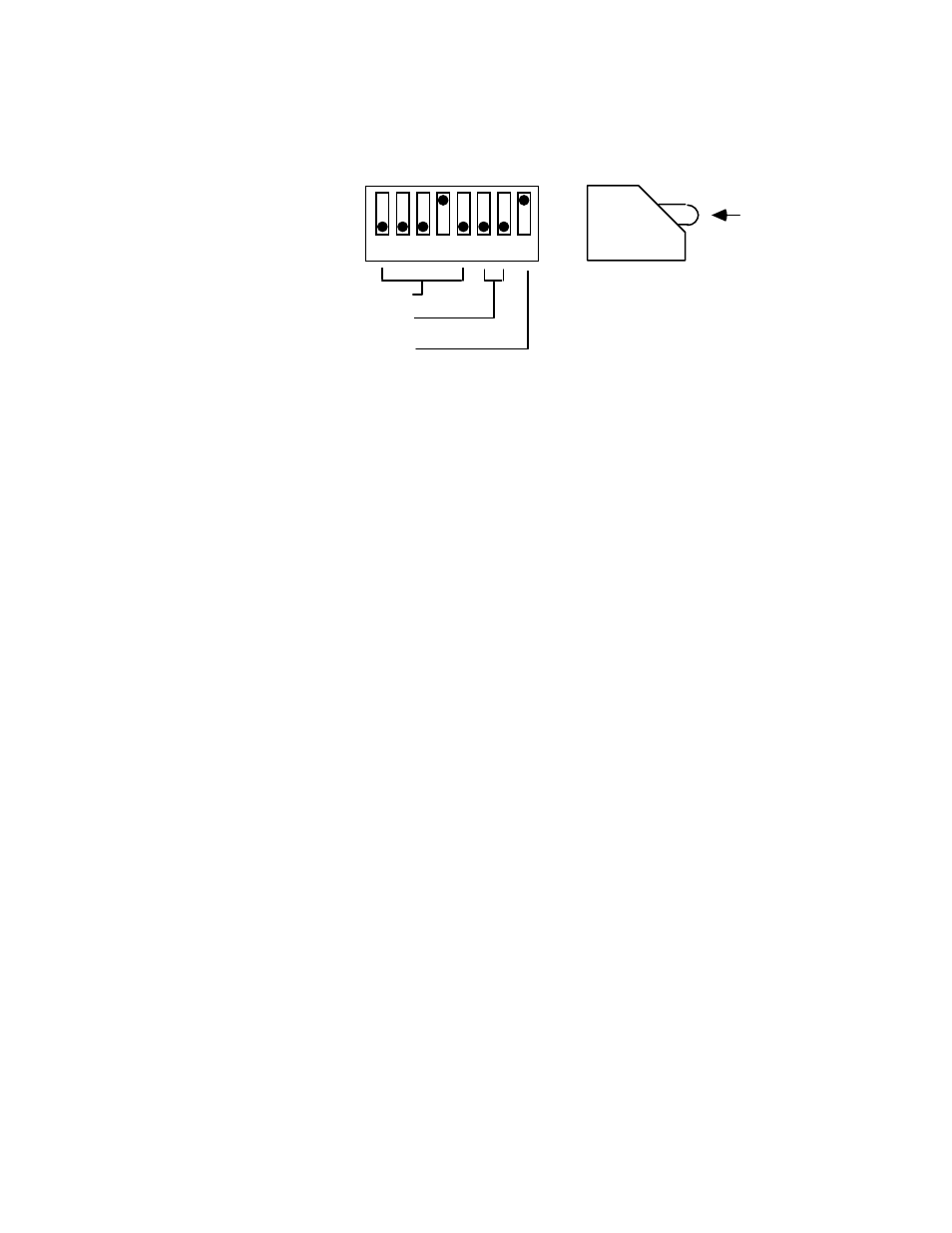
Figure 2-2. SW1 Factory Default Setting
IEEE Address = 8
Switch
Side
View
DOT
0
1
1 2 3 4 5 6 7 8
Dual Primary Addressing
Mode
Not Used
The bus terminator is determined by the last Bus Terminator (Yn) command sent
to the bus as described in Section 3. The bus terminator can be set to any of four
available options: CR only ( Y0), LF only (Y1), CR LF ( Y2), and LF CR ( Y3). On
initial power-up, the default value is ( Y2) CR L F. To change the power-up default
terminator, first set the terminator using the Yn command. Then save the selection
using the Save Configuration ( S1) command as described in Section 3. Refer to
section 2.3.3 for a discussion of the bus terminator.
2.3.1 Serial488/4 Addressing Modes
To provide transparent serial data communications, the Serial488/4
occupies either 1 or 2 primary addresses on the IEEE 488 bus, dependent
upon the addressing mode used. The two available addressing modes are
secondary and dual primary. One address is used for sending commands to
and receiving status from the Serial488/4. T he other addresses are used
exclusively for serial data transfer. The addressing mode is determined by
position 8 of SW1 (located on the rear panel). Switch position SW1-8 for
each mode is shown in Figure 2-4.
Examples are given at the end of this section to illustrate the
differences between the two modes and how each is used to communicate
with the Serial488/4.