Oversampling and line cycle rejection – Measurement Computing Personal Daq/3000 Series User Manual
Page 84
A-6 Signal Modes and System Noise
937492
Appendix A
A solution to high source impedance in relation to multiplexers involves the use of buffers. The term
buffer has several meanings; but in this case, buffer refers to an operational amplifier having high input
impedance but very low output impedance. Placing such a buffer on each channel (between the
transducer and the multiplexer) prevents the multiplexer’s stray capacitance from combining with the high
input impedance. This use of a buffer also stops transient signals from propagating backwards from the
multiplexer to the transducer.
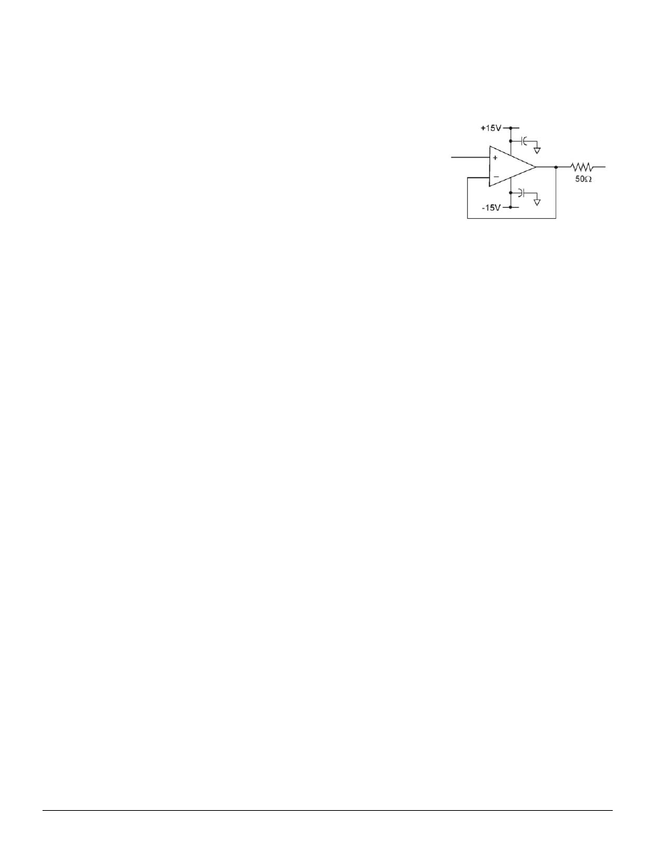
An example of a buffer is illustrated by the simple op-amp schematic
at the right. The op-amp should have a bandwidth between 8MHz and
50MHz, even if the signal being measured is DC. This allows the op-
amp to recover quickly from the DaqBoard’s input multiplexer charge
injection.
Note that characteristics of the op-amp (offset voltage, bias current,
etc.) should be chosen with serious consideration for the signal being
measured.
Personal Daq/3000 and PDQ30 systems do not have a buffer for each analog input channel, due to power
restrictions. Crosstalk is particularly troublesome when measuring high amplitude signals (+/-10V) along
with low level signals (+/- 100mV.) All temperature measurements are low level signals that use the +/-
100mV range of the Personal Daq.
If an acquisition’s scan group includes both high level signals and low level signals, here are some tips on
how to reduce the amount of crosstalk.
•
Use as much oversampling as possible.
•
Within the scan group, group high level signals together, group low level signals together
•
Place a shorted channel in the scan group between the high level signals and the low level
signals. The shorted channel should have the same gain as the last high level signal. This
may allow for a faster scan rate with less oversampling.
Oversampling and Line Cycle Rejection
The Personal Daq/3000 and PDQ30 allow for oversampling and line cycle rejection to be done. When the
units are put into oversampling mode, noise is reduced and ambient 60Hz or 50Hz pick up can be
rejected. When enabled, oversampling is adjustable from 2 to 16384. The more oversampling that is
done, the less noise present in the readings. Line cycle rejection is just another mode of oversampling
where 16384; 8192; 4096; etc. consecutive samples are averaged over one line cycle of 50Hz or 60Hz.
When oversampling is employed it is done for all analog channels in the scan group: voltage,
temperature, CJC, autozero, Personal Daq/3000 channels, and PDQ30 channels. Digital channels are not
oversampled. Increasing the amount of oversampling will drastically decrease the maximum allowable
scan rate. During acquisitions, the system controller reads each of the channel entries in the scan list and
measures each channel according to the desired channel number and gain. If oversampling is enabled, the
acquisition engine reads each of the channel entries in the scan list and takes multiple consecutive
measurements without changing the channel or gain. All consecutive 16-bit measurements are averaged
and then returned to the software.
In the case of line cycle rejection, the acquisition engine adjusts the conversion time of the ADC slightly
so that 16384; 8192; 4096; etc. samples will fit inside one line cycle of 50 Hz (20ms) or 60Hz (16.666ms).
When enabled, line cycle rejection can be applied to all analog channels in the scan list; or it can be
applied exclusively to thermocouple channels.