Measurement Computing Personal Daq/3000 Series User Manual
Page 54
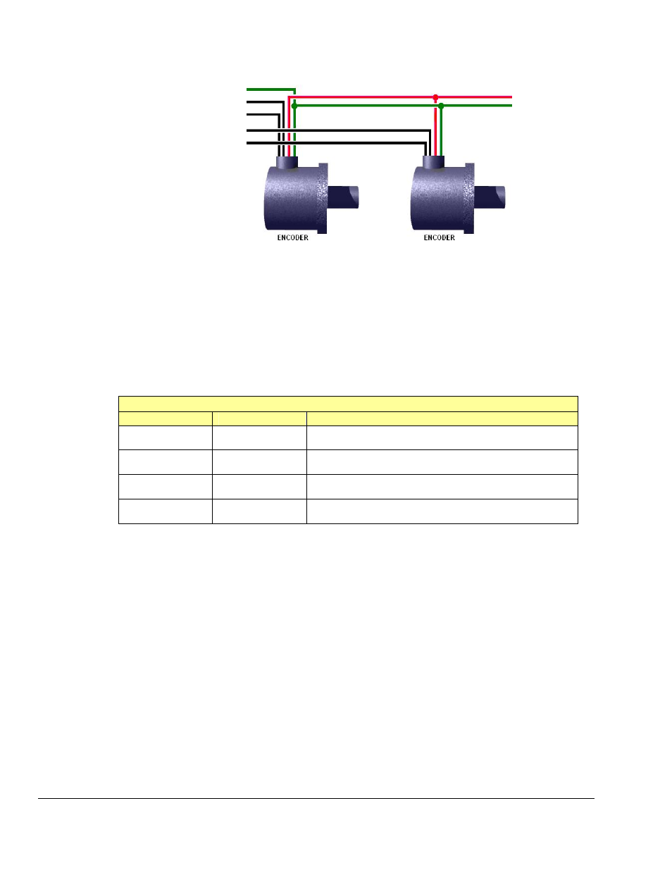
Wiring for 2 Encoders
The following figure illustrates single-ended connections for two encoders. Differential connections are
not applicable.
Ground (to Digital Common)
1
Counter 0 – To Encoder #1 “A”
Counter 1 – To Encoder #1 “B”
Counter 2 – To Encoder #2 “A”
Counter 3 – To Encoder #2 “B”
To External Power
To Ground
2
Two Encoders Connected to Personal Daq/3000
1
The ground depicted at the left is associated with Digital Common on the Personal Daq/3000 Series module.
2
The ground depicted at the right is associated with the external power source.
Connect two encoders to the 3000 Series device as shown in the table below. Each signal (A, B) can be
connected as a single-ended connection with respect to the common digital ground (GND). Both encoders
will need powered from an external power source (typically +5VDC).
Connect each encoder’s power input to the external power source. Connect the return to digital common
(GND) on the same source. The programming setup given below is just one example. Other setups are
possible.
Two Encoders – Programming Example Setup for Personal Daq/3000
Screw Terminal
Connects to:
Example Programming Setup
TB5, Terminal 2
Counter 0 (CNT0)
Encoder #1 – A
Encoder Mode, 1X option, 16-bit counter, Latch on SOS
TB5, Terminal 1
Counter 1 (CNT1)
Encoder #1 – B
Period Mode, 1Xperiod option, 16-bit counter, Map channel
doesn’t gate, Ticksize to 20833 ns
TB4, Terminal 2
Counter 2 (CNT2)
Encoder #2 – A
Encoder Mode, 2X option, 16-bit counter, Latch on SOS
TB4, Terminal 1
Counter 3 (CNT3)
Encoder #2 – B
Period Mode, 1Xperiod option, 16-bit counter, Map channel
doesn’t gate, Ticksize to 2083.3 ns
With the encoders connected in this manner there is no relative positioning information available on
encoder #1 or #2 since there is no Z signal connection for either. Therefore only distance traveled and
velocity can be measured for each encoder.
5-20 Counter Input Modes
887894
Personal Daq/3000 Series User’s Manual