System noise, Averaging, Analog filtering – Measurement Computing Personal Daq/3000 Series User Manual
Page 83: Input, Source impedance, Crosstalk
System Noise
Laboratory and industrial environments often have multiple sources of electrical noise. An AC power line
is a source of 50/60 Hz noise. Heavy equipment (air conditioners, elevators, pumps, etc.) can be a source
of noise, particularly when turned on and off. Local radio stations are a source of high-frequency noise,
and computers and other electronic equipment can create noise in a multitude of frequency ranges. Thus,
an absolute noise-free environment for data acquisition is not realistic. Fortunately, noise-reduction
techniques such as averaging, filtering, differential voltage measurement, and shielding are available to
reduce noise to an acceptable level.
Averaging
Certain acquisition programs apply averaging after several samples have been collected. Depending on
the nature of the noise, averaging can reduce noise by the square root of the number of averaged samples.
Although averaging can be effective, it suffers from several drawbacks. Noise in measurements only
decreases as the square root of the number of measurements — reducing RMS noise significantly may
require many samples. Thus, averaging is suited to low-speed applications that can provide many
samples.
Note: Only random noise is reduced or eliminated by averaging. Averaging does not reduce or eliminate
periodic signals. Refer to the section, Oversampling and Line Cycle Rejection (page A-6 ).
Analog Filtering
A filter is an analog circuit element that attenuates an incoming signal according to its frequency. A low-
pass filter attenuates frequencies above the cutoff frequency. Conversely, a high-pass filter attenuates
frequencies below the cutoff. As frequency increases beyond the cutoff point, the attenuation of a single-
pole, low-pass filter increases slowly. Multi-pole filters provide greater attenuation beyond the cutoff
frequency but may introduce phase (time delay) problems that could affect some applications.
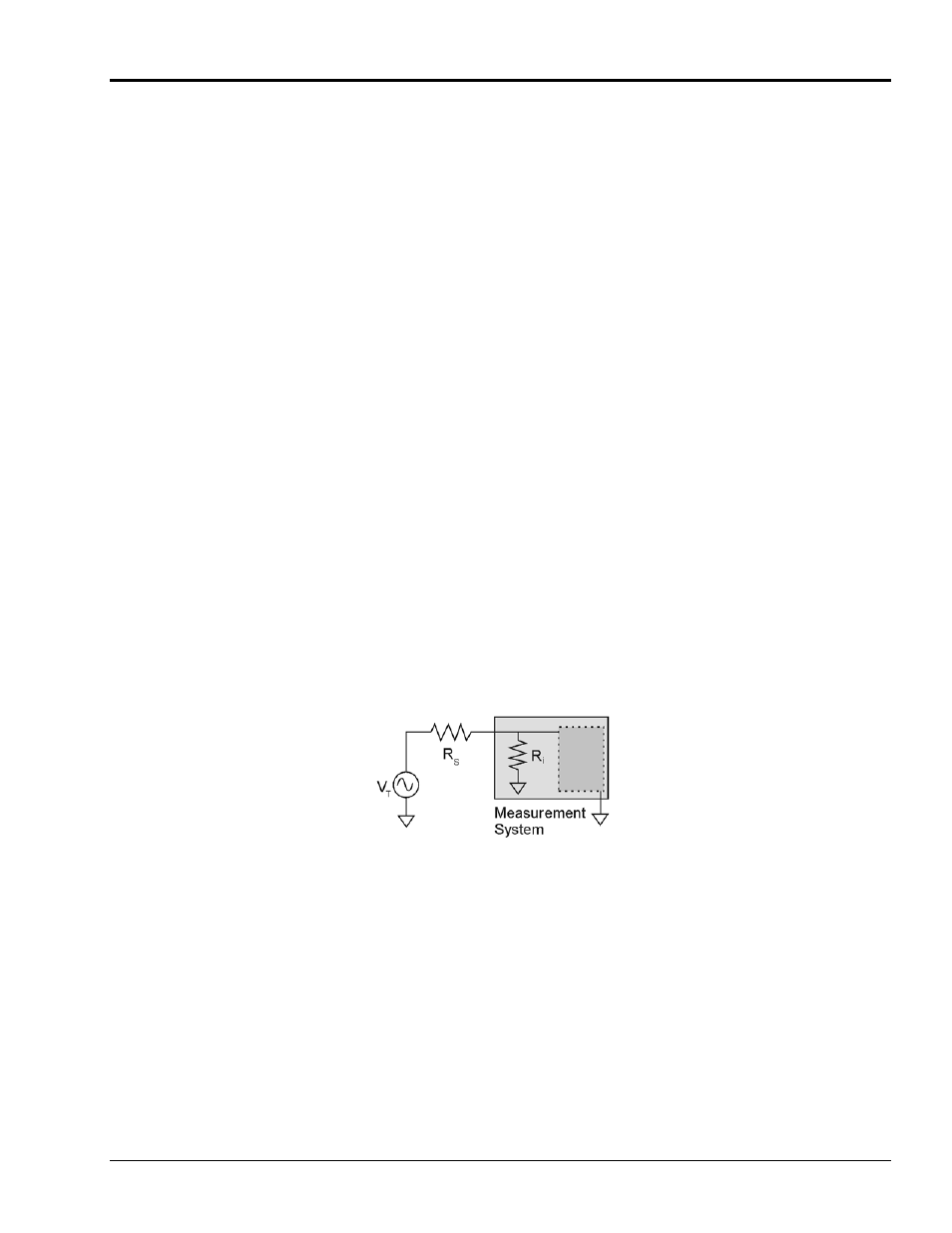
Input
and
Source Impedance
As illustrated in the following figure, input impedance (R
i
) of a measurement system combines with the
transducer’s source impedance (R
s
) forming a voltage divider. This divider distorts the voltage being read.
The actual voltage read is represented by the equation: V
ADC
= V
T
× R
i
/ (R
s
+ R
i
)
With input impedance (R
i
) of 10 M
Ω, which is a realistic value for many measurement systems, a low
source impedance (R
s
) of less than 100
Ω usually presents no problem. Signals from sources with
impedance greater than 100
Ω should have appropriate signal conditioning.
Crosstalk
Crosstalk is a type of noise related to source impedance and capacitance, in which signals from one
channel leak into an adjacent channel, resulting in interference or signal distortion. The impact of source
impedance and stray capacitance can be estimated by using the following equation.
T = RC
Where T is the time constant, R is the source impedance, and C is the stray capacitance.
High source (transducer) impedance can be a problem in multiplexed A/D systems. When using more
than 1 channel, the channel input signals are multiplexed into the A/D. The multiplexer samples one
channel and then switches to the next channel. A high-impedance input interacts with the multiplexer’s
stray capacitance and causes crosstalk and inaccuracies in the A/D sample.
Appendix A
937492
Signal Modes and System Noise A-5