Controlling analog, digital, and timer outputs – Measurement Computing Personal Daq/3000 Series User Manual
Page 58
Controlling Analog, Digital, and Timer Outputs
Each setpoint can be programmed with an 8-bit digital output byte and corresponding 8-bit mask byte.
When the setpoint criteria has been met, the P2C digital output port can be updated with the given byte and
mask. Alternately, each setpoint can be programmed with a 16-bit DAC update value, any one of the 4
DAC outputs can be updated in real time. Any setpoint can also be programmed with a timer update value.
In hysteresis mode each setpoint has two forced update values. Both update values can drive the same
output target; i.e, DAC, timer, or P2C digital output port. In hysteresis mode the outputs do not change
when the input values are inside the window. There is one update value that gets applied when the input
values are less than the window and a different update value that gets applied when the input values are
greater than the window.
Update on True and False uses two update values. There is one update value that gets applied when the
specified criteria is met (True) and a different update value that gets applied when the specified criteria is
not met (False). The update values can drive DACs, P2C, or timer outputs.
Example: Setpoint Detection on a Totalizing Counter
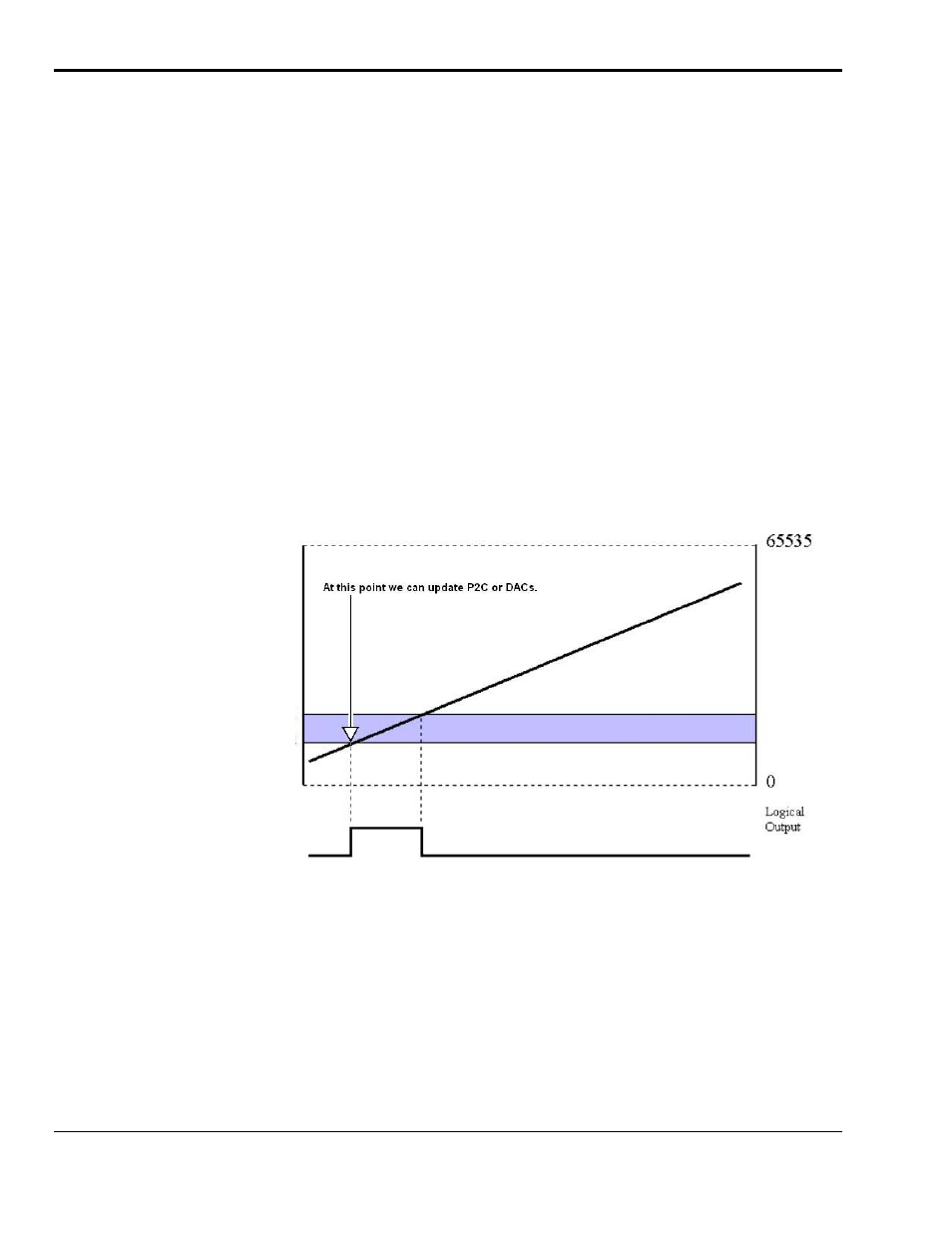
In the following figure Channel 1 is a counter in totalize mode. Two setpoints are used to define a point of
change for Detect 1 as the counter counts upward. The detect output will be high when inside the window
(greater than Limit B (the low limit) but less than Limit A (the high limit). In this case, the Channel 1
setpoint is defined for the 16 lower bits of channel 1’s 32-bit value. The P2C digital output port could be
updated on a True condition (the rising edge of the Detection signal). Alternately, one of the DAC output
channels, or timer outputs, could be updated with a value.
Limit A
Limit B
Detection
Channel 1 in Totalizing Counter Mode, Inside the Window Setpoint
The detection circuit works on data that is put into the acquisition stream at the scan rate. This data is
acquired according to the pre-acquisition setup (scan group, scan period, etc.) and returned to the PC.
Counters are latched into the acquisition stream at the beginning of every scan. The actual counters may be
counting much faster than the scan rate and therefore only every 10
th
, 100
th
, or n
th
count will show up in the
acquisition data. Therefore it is possible to set a small detection window on a totalizing counter channel
and have the detection setpoint “stepped over” since the scan period was too long. Even though the counter
value stepped into and out of the detection window, the actual values going back to the PC may not. This
is true no matter what mode the counter channel is in.
6-4 Setpoint Configuration for Output Control
887894
Personal Daq/3000 Series User’s Manual