Personal daq/3000 series installation guide, Personal daq/3000 series quick start, Usb1-mhz, 16-bit multifunction modules – Measurement Computing Personal Daq/3000 Series User Manual
Page 7: Before you get started, Step 1 – install software, Step 2 – connect signal lines and hardware
1136-0940, rev 3.0
324400D-01 Printed in Hungary
Personal Daq/3000 Series Quick Start
USB1-MHz, 16-Bit Multifunction Modules
Before you get started
Verify that you have the following items.
•
Personal Daq/3000 Series Device(s)
•
Data Acquisition CD
•
Monitor: SVGA, 1024 x 768 screen resolution
•
Computer that meets or exceeds the following:
Intel
™
Pentium, 1 GHz or equivalent; 10 GB disk space;
Available USB Port; USB cable; one of the following
Microsoft
®
Operating Systems and indicated memory or
higher:
WindowsXP – 128 MB memory
Windows2000 – 128 MB memory
Windows Vista – 1 GB memory
Step 1 – Install Software
IMPORTANT: Software must be installed before installing hardware.
1. Place the Data Acquisition CD into the CD-ROM drive. Wait for PC to auto-run the CD. This may take a few moments,
depending on your PC. If the CD does not auto-run, use the Desktop’s Start/Run/Browse feature and run the Setup.exe.
2. After the intro-screen appears, follow the screen prompts.
Step 2 – Connect Signal Lines and Hardware
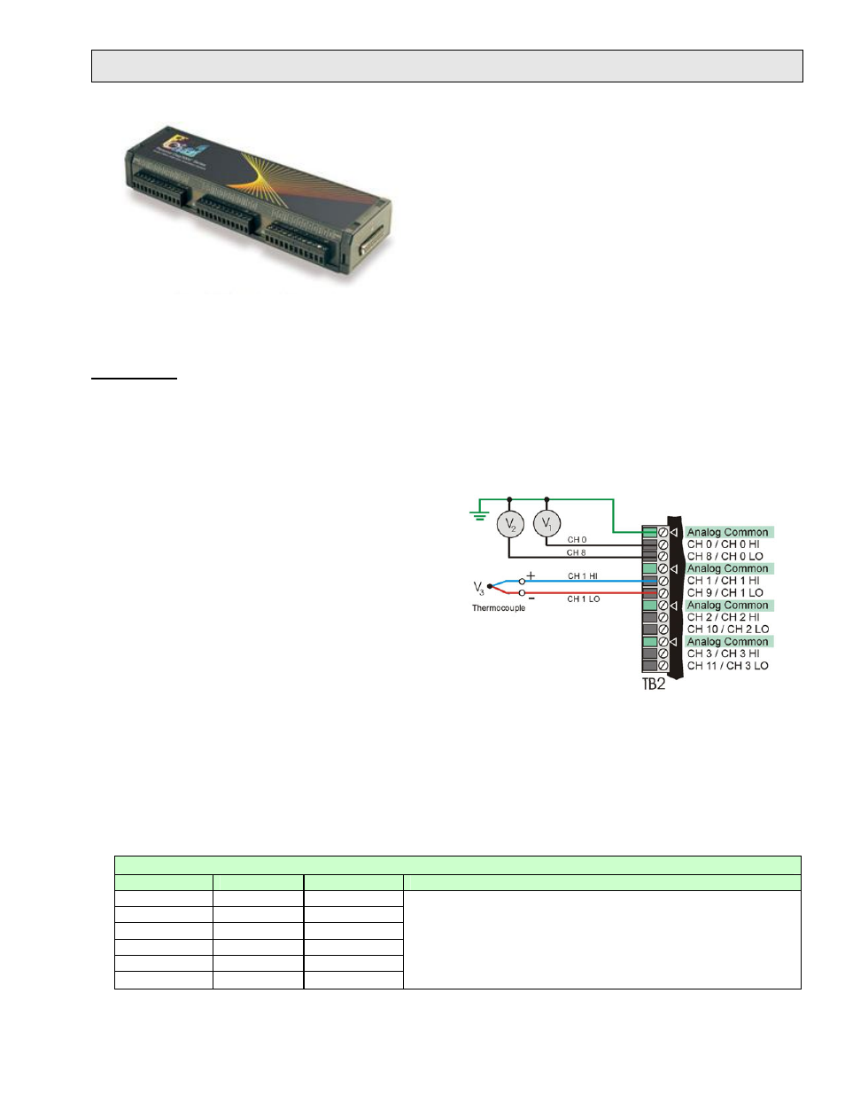
1. Connect signal lines to the removable screw-terminal
blocks.
Voltage signals can be connected using the Single-Ended
method. In the figure, voltage source V1 is connected to
Channel 0 and to analog common; and voltage source V2
is connected to Channel 8 and the same analog common
connection.
The figure shows voltage V3 resulting from a
thermocouple. In this case Differential mode is being
used. The HI (+) line from the thermocouple is shown
connected to Channel 1 HI; and the LO (negative) side is
connected to Channel 1 LO. Notice that Channel 1 LO is the same screw terminal connection that would be used for CH
9 Single-Ended.
To differentially connect a thermocouple; connect the red T/C wire to the channel’s Low (L) connector. Connect the
other color wire to the channel’s High (H) connector.
PDQ30 is an optional analog expansion module that can be used to add an additional 48 SE (or 24 DE) analog inputs.
PDQ30 is not to be connected to a live device. Unplug the USB cable from the host PC prior to connecting the
PDQ30. Refer to user’s manual for regarding PDQ30 issues.
Power Consumption (Typical)
1
Model
Consumption
2
TR-2
2
Notes
/3000
2500 mW
Recommended
/3001
3000 mW
Required
/3005
2000 mW
Optional
/3000 & PDQ30
2900 mW
Required
/3001 & PDQ30
3400 mW
Required
/3005 & PDQ30
2400 mW
Recommended
1
The power consumption listed is for a single /3000 Series device, or for a
single device connected to a PDQ30 expansion module.
2
A power adapter (TR-2) will be required if the USB port cannot supply
adequate power. When meeting USB2 standards, a USB port can supply
2500 mW (nominal at 5V, 500 mA).