Wiring for 1 encoder – Measurement Computing Personal Daq/3000 Series User Manual
Page 52
Wiring for 1 Encoder
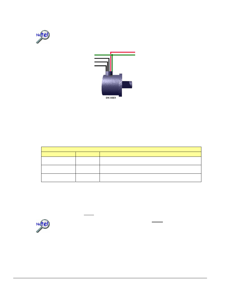
The following figure illustrates connections for one encoder to a Personal Daq/3000 module.
The “A” signal must be connected to an even-numbered channel and the associated
“B” signal must be connected to the next [higher] odd-numbered channel. For example,
if “A” were connected to Counter 0, then “B” would be connected to Counter 1.
Ground (to Digital Common)
1
Counter 0 – To Encoder “A”
Counter 1 – To Encoder “B”
Counter 2 – To Encoder “Z”
To External Power
To Ground
2
Encoder Connections to pins on the Personal Daq/3000
1
The ground depicted at the left is associated with Digital Common on the Personal Daq/3000 Series module.
2
The ground depicted at the right is associated with the external power source.
In addition to the previous figure, the following table indicates how to connect a single encoder to a 3000
Series device. Each signal (A, B, Z) can be connected as a single-ended connection with respect to the
common ground. The encoder will need to be powered from an external power output (typically +5VDC).
Connect the encoder’s power input to the power source and connect the return to digital common (GND) of
that source.
The programming setup given below is just a representative of possible options.
Single Encoder – Programming Example Setup for Personal Daq/3000 Series Module
Screw Terminal
Connects to:
Example Programming Setup
TB5, Terminal 2
Counter 0 (CNT0)
Encoder – A
Encoder Mode, 4X option, 16-bit counter, Latch on SOS, Map channel
Clears the counter, set Map channel to CTR2.
TB5, Terminal 1
Counter 1 (CNT1)
Encoder – B
Period Mode, 1Xperiod option, 16-bit counter, Map channel doesn’t
gate, Ticksize to 208.3 ns.
TB4, Terminal 2
Counter 2 (CNT2)
Encoder – Z Counter in Totalize mode, stop-at-the-top, 16-bit counter.
If the encoder stops rotating, but is vibrating [due to the machine it is mounted to], the debounce feature
can be used to eliminate false edges. An appropriate debounce time can be chosen and applied to each
encoder channel. Refer to the Debounce Module section on page 5-1 for additional information regarding
debounce times.
Relative position and velocity can be obtained from the encoder. However, during an acquisition, data that
is relative to the Z-position cannot be obtained until the encoder locates the Z-reference.
During an acquisition, data that is relative to the Z-position cannot be obtained until the
encoder locates the Z-reference.
Note that the number of Z-reference crossings can be tabulated. If the encoder was turning in only one
direction, then the Z-reference crossings will equal the number of complete revolutions. This means that
the data streaming to the PC will be relative position, period = 1/velocity, and revolutions.
5-18 Counter Input Modes
887894
Personal Daq/3000 Series User’s Manual