Measurement Computing DaqBoard 3000USB Series User Manual
Page 82
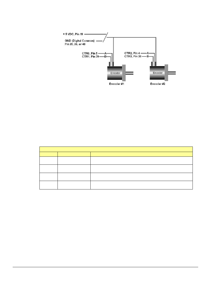
Wiring for 2 Encoders
The following figure illustrates single-ended connections for two encoders. Differential connections are
not applicable.
Two Encoders Connected to pins on the SCSI Connector*
* Connections can instead, be made to the associated screw-terminals of a connected TB-100 terminal
connector option.
Connect two encoders to the 3000USB Series board as shown in the table below. Each signal (A, B) can
be connected as a single-ended connection with respect to the common digital ground (GND). Both
encoders can draw their power from the +5V power output (pin 19) on the 68-pin SCSI connector.
Connect each encoder’s power input to +5V power. Connect the return to digital common (GND) on the
same connector. Make sure that the current output spec is not violated. The programming setup given
below is just a representative of possible options.
Two Encoders – Programming Example Setup
SCSI Pin
Connects to:
Example Programming Setup
Pin 5
(CTR0)
Encoder #1 – A
Encoder Mode, 1X option, 16-bit counter, Latch on SOS
Pin 39
(CTR 1)
Encoder #1 – B
Period Mode, 1Xperiod option, 16-bit counter, Map channel doesn’t gate,
Ticksize to 20833 ns
Pin 4
(CTR2)
Encoder #2 – A
Encoder Mode, 2X option, 16-bit counter, Latch on SOS
Pin 38
(CTR3)
Encoder #2 – B
Period Mode, 1Xperiod option, 16-bit counter, Map channel doesn’t gate,
Ticksize to 2083.3 ns
With the encoders connected in this manner there is no relative positioning information available on
encoder #1 or #2 since there is no Z signal connection for either. Therefore only distance traveled and
velocity can be measured for each encoder.
5-20 Counter Input Modes
887794
DaqBoard/3000USB Series User’s Manual