Measurement Computing DaqBoard 3000USB Series User Manual
Page 113
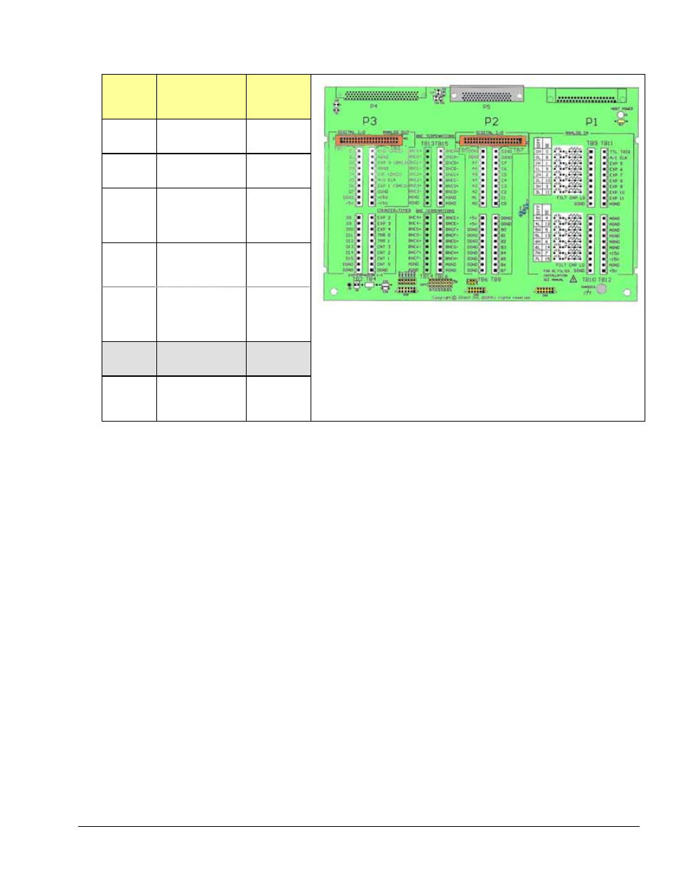
In general, the following terminal block-to-signal relationships apply:
DBK215
Terminal
Blocks
Used for . . .
Alternative
TB9
TB10
ANALOG INPUT
BNC 0 thru 7
TB11
TB12
ANALOG INPUT
N/A
TB5
TB6
TB7
TB8
DIGITAL I/O
N/A
TB13**
TB14**
ANALOG INPUT
BNC Channels
0 thru 7**
TB9,TB10
TB15
TB16
(Note 1)
USER
CONFIGURABLEB
NC Channels
A thru H
(See Note 1)
TB1
TB2
-- Not Used---
N/A
TB3
TB4
PULSE/
FREQUENCY
ANALOG OUTPUT
N/A
DBK215 Board
*
P4 is used for connecting to DaqBoard/2000 Series devices.
**
TB13 and TB14 are “virtual” terminal blocks which are routed in the printed circuit board to TB9 and TB10. The TB13 and TB14
silk-screened locations on the DBK215 board do not have physical screw terminal blocks.
Note 1: TB15 and TB16 are used for optional user-configured BNC connectors A through H. These connectors can be configured on a
per-channel basis as Analog [Input or Output], Digital I/O, or Counter/Timer. When BNC A through H are used, the user must
route wires from the “BNC routing terminal blocks” (TB15 and TB16) to the appropriate functional TB termination points.
Accessory Wire Kit, p/n 1139-0800 includes jumper wires and a screwdriver.
The following pages correlate the DBK215 terminal block connectors with the 68-pin SCSI connector.
Appendix A
886994
DBK215 A-7