System noise, Analog filtering, Input – Measurement Computing DaqBoard 3000USB Series User Manual
Page 125: Source impedance, Crosstalk
Appendix B
938390
Signal Modes and System Noise B-5
Analog Filtering
A filter is an analog circuit element that attenuates an incoming signal according to its frequency. A low-
pass filter attenuates frequencies above the cutoff frequency. Conversely, a high-pass filter attenuates
frequencies below the cutoff. As frequency increases beyond the cutoff point, the attenuation of a single-
pole, low-pass filter increases slowly. Multi-pole filters provide greater attenuation beyond the cutoff
frequency but may introduce phase (time delay) problems that could affect some applications.
Input
and
Source Impedance
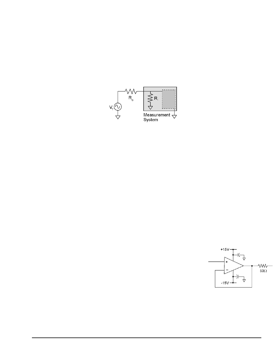
As illustrated in the following figure, input impedance (R
i
) of a measurement system combines with the
transducer’s source impedance (R
s
) forming a voltage divider. This divider distorts the voltage being read.
The actual voltage read is represented by the equation: V
ADC
= V
T
× R
i
/ (R
s
+ R
i
)
With input impedance (R
i
) of 10 MΩ, which is a realistic value for many measurement systems, a low
source impedance (R
s
) of less than 100Ω usually presents no problem. Signals from sources with
impedance greater than 100Ω should have appropriate signal conditioning.
Crosstalk
Crosstalk is a type of noise related to source impedance and capacitance, in which signals from one channel
leak into an adjacent channel, resulting in interference or signal distortion. The impact of source impedance
and stray capacitance can be estimated by using the following equation.
T = RC
Where T is the time constant, R is the source impedance, and C is the stray capacitance.
High source (transducer) impedance can be a problem in multiplexed A/D systems. When using more than
1 channel, the channel input signals are multiplexed into the A/D. The multiplexer samples one channel and
then switches to the next channel. A high-impedance input interacts with the multiplexer’s stray
capacitance and causes crosstalk and inaccuracies in the A/D sample.
A solution to high source impedance in relation to multiplexers involves the use of buffers. The term buffer
has several meanings; but in this case, buffer refers to an operational amplifier having high input impedance
but very low output impedance. Placing such a buffer on each channel (between the transducer and the
multiplexer) prevents the multiplexer’s stray capacitance from combining with the high input impedance.
This use of a buffer also stops transient signals from propagating backwards from the multiplexer to the
transducer.
An example of a buffer is illustrated by the simple op-amp schematic at the
right. The op-amp should have a bandwidth between 8MHz and 50MHz,
even if the signal being measured is DC. This allows the op-amp to
recover quickly from the DaqBoard’s input multiplexer charge injection.
Note that characteristics of the op-amp (offset voltage, bias current, etc.)
should be chosen with serious consideration for the signal being measured.
DaqBoard/3000USB Series boards do not have a buffer for each analog
input channel, due to power restrictions. Crosstalk is particularly troublesome when measuring high
amplitude signals (+/-10V) along with low level signals (+/- 100mV.) All temperature measurements are
low level signals that use the +/- 100mV range of the boards.