Connections, Connections …… 1-3 – Measurement Computing DaqBoard 3000USB Series User Manual
Page 30
1-4 Device Overviews
988093
DaqBoard/3000USB Series User’s Manual
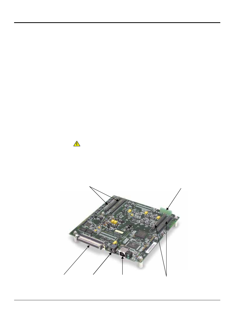
Connections
SCSI - 68 pin (P5)
The 68-pin SCSI connector includes pins for the following. Chapter 2 includes a pinout.
o
16SE / 8DE analog
inputs (Ch 0 thru 15)
o
24 digital I/O
o
4 counter inputs
o
2 timer outputs
o
A/D pacer clock I/O
o
DAC pacer clock I/O
o
TTL trigger
o
self calibration
+5 VDC
o
o
analog commons
o
digital commons
o
up to four DACs (according to
board model)
You can connect a TB-100 screw-terminal board or a DBK215 BNC screw-terminal
module to the SCSI connector via one of the following cables.
CA-G55
CA-G56
CA-G56-6
68-conductor ribbon expansion cable. 3 feet.
68-conductor shielded expansion cable. 3 feet.
68-conductor shielded expansion cable. 6 feet.
40-pin Headers
(J5, J6, J7, J8)
Four 40-pin headers (J5 through J8) provide an alternative connection to the signals of the
SCSI connector. Also, for the /3031USB and /3035USB, the J5 and J6 headers accept
additional analog input for a total of 64 Single Ended, or 32 Differential. You can obtain a
male DB37 connector for each header by connecting a CA-248 (40-pin to male DB-37
cable) to each header.
9-slot Screw
Terminal (TB7)
The on-board screw terminal connector (TB7) can be used to connect up to four
thermocouple inputs. TB7 uses the following analog channels [which can also be
accessed via the SCSI connector and J5] to obtain its 4 differential channels:
TC CH0: CH 0 (+); CH 8 (-) TC CH1: CH 1 (+); CH 9 (-) TC CH2: CH 2 (+); CH 10 (-)
TC CH3: CH 3 (+); CH 11 (-)
As stated in the WARNINGS of the pinout and connection chapter
(Chapter 2), care must be taken to avoid redundant connections!
External
Power
Although the 3000USB Series boards are powered via a USB port on a host PC, an
external power connector is available for cases in which the host PC’s USB port cannot
supply adequate power, or for when the user prefers a separate power source. The TR-2
is an optional power supply available for this purpose. The TR-2 plugs into a standard
120VAC outlet and will supply 9VDC, 1 amp power to the board via its external power
connector (see figure).
4 0 - P i n H e a d e r s 4 C h a n n e l T C
J 6 a n d J 5 T e r m i n a l B o a r d ( T B 7 )
S C S I ( P 5 ) E x t e r n a l P o we r U S B 2 . 0 P o r t 4 0 - P i n H e a d e r s
6 8 - P i n J 8 a n d J 7
Location of Connectors