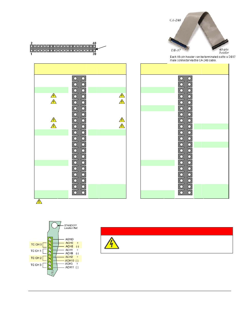
J5 and j6, 40-pin headers for analog channels, Tb7, 4-channel thermocouple terminal block, Warning – Measurement Computing DaqBoard 3000USB Series User Manual
Page 19
DaqBoard/3000USB Series Installation Guide
968492
IG-13
J5 and J6, 40-Pin Headers for Analog Channels
Note: All channels are available for DaqBoard/3031USB and /3035USB.
Channels 16 through 63 are not available for DaqBoard/3001USB
and /3005USB.
This edge of the header is closest to
the board’s center. Note that pins 2
and 40 are labeled on the board
overlay.
Analog CH.
Pin
J5
Pin
Analog CH.
Analog CH.
Pin
J6
Pin
Analog CH.
CH 27
1
2
CH 19
CH 43
1
2
CH 59
CH 26
3
4
CH 18
CH 35
3
4
CH 51
Analog Com.
5
6
Analog Com.
Analog Com.
5
6
CH 58
CH 3
7
8
CH 11
CH 42
7
8
CH 50
CH 2
9
10
CH 10
CH 34
9
10
CH 57
CH 17
11
12
CH 25
Analog Com.
11
12
CH 49
CH 16
13
14
CH 24
CH 41
13
14
CH 56
CH 1
15
16
CH 9
CH 33
15
16
CH 48
CH 0
17
18
CH 8
CH 40
17
18
Analog Com.
Analog Com.
19
20
Analog Com.
CH 32
19
20
CH 63
CH 23
21
22
CH 31
CH 47
21
22
CH 55
CH 22
23
24
CH 30
CH 39
23
24
Analog Com.
CH 7
25
26
CH 15
CH 46
25
26
CH 62
CH 6
27
28
CH 14
CH 38
27
28
CH 54
Analog Com.
29
30
CH 21
Analog Com.
29
30
CH 61
CH 29
31
32
CH 20
CH 45
31
32
CH 53
CH 28
33
34
CH 5
CH 37
33
34
CH 60
CH 13
35
36
CH 4
CH 44
35
36
CH 52
CH 12
37
38
Analog Com.
CH 36
37
38
Analog Com.
Analog Com.
39
40
Analog Com.
Analog Com.
39
40
Analog Com.
For Analog Channels 0, 1, 2, 3, 8, 9, 10, and 11: Read the following WARNING which applies to their use
as thermocouple channels.
TB7, 4-Channel Thermocouple Terminal Block
WARNING !
Before connecting TC wires, ensure that the associated
analog channels are not in use. Failure to do so could
possibly cause equipment damage and/or personal injury.
The TB7 terminal block can be used to connect up to 4 thermocouples. The
first TC channel makes use of Analog Channel 0 for its positive (+) lead and
Analog Channel 8 for its negative (-) lead. The second TC channel uses
analog Channels 1 and 9, and so on, as indicated in the pinout to the left.