Measurement Computing CIO-DAS6402/12 User Manual
Page 7
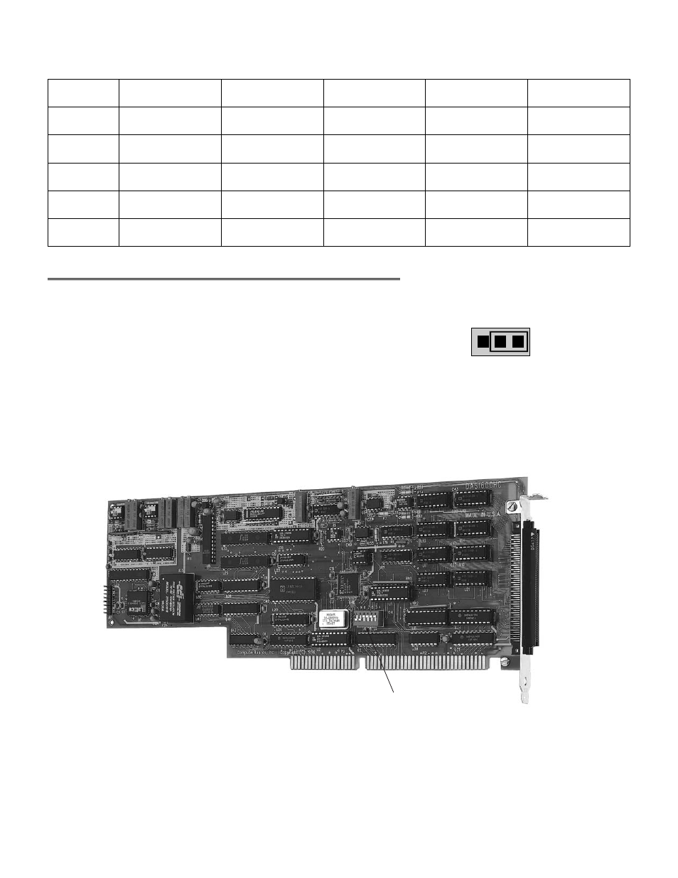
Table 3-1. D/A Analog Range Switch Settings
Range
SW 1
SW 2
SW 3
SW 4
SW 5
DN
DN
UP
DN
UP
0 to 2.5 V
UP
DN
UP
DN
UP
0 to 5.0 V
DN
UP
UP
DN
UP
0 to 10 V
DN
DN
DN
UP
DN
±2.5 V
UP
DN
DN
UP
DN
±5.0 V
DN
UP
DN
UP
DN
±10.0 V
3.3
D/A UPDATE MODE (CIO-DAS6402/16 ONLY)
The analog outputs can be configured to update independently or
simultaneously. The update mode is set by a jumper on the
CIO-DAS6402/16. This jumper is shown in Figure 3-5.
Place the jumper on the XFER side for simultaneous update. Place the
jumper on the UPDATE side for independent operation.
Figure 3-5. D/A Update Mode Select Jumper
Figure 3-6. CIO-DAS6402/12 Base Address Switches Location
3
XF ER
U PD AT E
C IO -D A S 6 4 0 2 /1 6 D /A
U P D AT E M O D E S E L E C T
(S H O W N IN S IM U LTA N E O U S U P D AT E M O D E )
Base Address Switch