2 low pass filters – Measurement Computing CIO-DAS6402/12 User Manual
Page 30
For a given attenuation, pick a resistor and call it
R2, the use this formula to calculate R1.
R1 = (A-1) x R2
Digital inputs often require the use of voltage dividers. For example, if you wish to measure a digital signal that is at 0 volts when
off and 24 volts when on, you cannot connect that directly to a digital input. The voltage must be dropped to 5 volts max when on.
The attenuation is 24:5 or 4.8.
Using the equation above, if R2 is 1K, R1 = (4.8
−1) x 1000 = 3.8K.
Remember that a TTL input is 'on' when the input voltage is greater than 2.5 volts.
NOTE
The resistors, R1 and R2, are going to dissipate power in the divider circuit according to the equation W = I
2
x R;
(Current (I) = Voltage/Resistance). The higher the value of the resistance (R1 + R2), the less power dissipated
by the divider circuit. Here is a simple rule:
For attenuation of <5:1, no resistor should be less than 10K.
For attenuation of > 5:1, no resistor should be less than 1K.
7.2
LOW PASS FILTERS
A low pass filter is placed on the signal wires between a signal and an A/D board. It stops frequencies greater than the cutoff
frequency from entering the A/D board's analog or digital inputs.
The cutoff frequency is that frequency above which no variation of voltage with respect to time may enter the circuit. For example,
if a low pass filter had a cutoff frequency of 30 Hz, the kind of interference associated with line voltage (60 Hz) would be filtered
out but a signal of 25 Hz would be allowed to pass.
In a digital circuit, a low-pass filter is often used to filter an input
from a momentary contact button or relay.
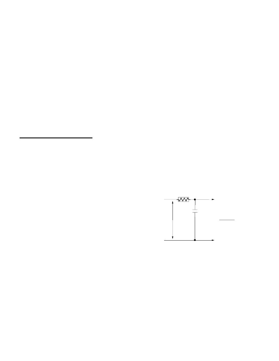
A simple low-pass filter may be constructed from one resistor (R)
and one capacitor (C). The cutoff frequency is determined according
to the formulas below: (Use
π= 3.14, R = ohms, C = Farads.)
1
Fc = --------------
2 *
π * R * C
1
R = ----------------
Figure 7-2. Low-Pass Filter Theory
2*
π * C * Fc
26
SIGNAL HIGH
SIGNAL LOW
A/D BOARD
HIGH INPUT
A/D BOARD
LOW INPUT
SIGNAL
VOLTS
LOW PASS FILTER
R
C
F
C
=
2*P i*R *C
1