4 analog connections 4.1 analog inputs – Measurement Computing CIO-DAS6402/12 User Manual
Page 10
4 ANALOG CONNECTIONS
4.1
ANALOG INPUTS
The following section provides explanations and helpful hints regarding analog input connections. This section is designed to help
you achieve the optimum performance from your CIO-DAS6402 series board.
Prior to jumping into actual connection schemes, you should have at least a basic understanding of Single-Ended/Differential inputs
and system grounding/isolation. If you are already comfortable with these concepts you may wish to skip to the next section (on
wiring configurations).
4.1.1
SINGLE-ENDED AND DIFFERENTIAL INPUTS
The CIO-DAS6402 provides either 32 differential or 64 single-ended input channels.
4.1.2
SINGLE-ENDED INPUTS
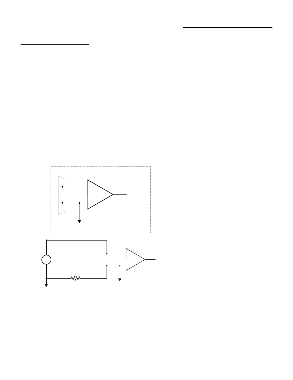
A single-ended input measures the voltage between the input signal and ground. In this case, in single-ended mode the
CIO-DAS6402 measures the voltage between the input channel and LLGND. The single-ended input configuration requires only
one physical connection (wire) per channel and allows the CIO-DAS6402 to monitor more channels than the (2-wire) differential
configuration using the same connector and onboard multiplexor. However, since the CIO-DAS6402 is measuring the input voltage
relative to its own low level ground, single-ended inputs are more susceptible to both EMI (Electro Magnetic Interference) and any
ground noise at the signal source. Figure 4-1 shows the theory of single-ended input configuration
Figure 4-1. Single-Ended Voltage Input Theory
6
+
-
In p ut
A m p
To A /D
S in g le-E n ded Inp ut
I/O
C o n n e c tor
LL G N D
C H IN
+
-
In p u t
A m p
To A /D
LL G N D
C H IN
~
1
2
V s
V s + V g 2 - V g 1
A n y v o ltag e diffe re n tia l b e tw e e n g ro u n d s
g 1 a n d g 2 s h o w s u p a s a n e rro r sig n a l
a t th e in pu t a m p lifie r
S in g le -e n de d in p u t w ith C o m m o n M o d e Vo lta g e
g
g