8 trigger control/ dac range select register – Measurement Computing CIO-DAS6402/12 User Manual
Page 25
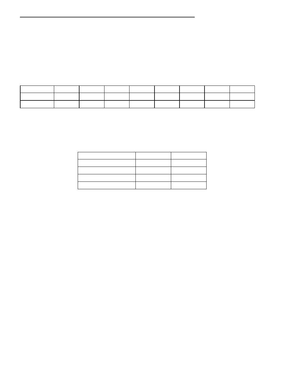
5.8
TRIGGER CONTROL/ DAC RANGE SELECT REGISTER
Triggering and Gating are digital means to control pacing. Triggering means that an active edge on the DI1 pin will start the A/D
Pacer. When the active edge occurs, the state of the pin is Don't Care. Gating means that a digital level on the DI1 pin will start or
stop the A/D Pacer; when the gate is active, A/D conversions are enabled. When the gate is inactive, A/D conversions are
suspended but they will resume when the gate returns to its active state. Gating and triggering both share DI1 pin and thus are
mutually exclusive. External Pacing, where each A/D conversion is started by an external signal, is tied to the DI0 pin. This means
that External Pacing can be combined with a Trigger/Gate function.
BASE ADDRESS +10
Example, 30Ah, 778 Decimal
WRITE
TRG0
CTR0
-
-
DAC0R0
DAC0R1
DAC1R0
DAC1R1
COMPATIBLE
T/G EN
T/G SEL
T/G POL
PRETRIG
DAC0R0
DAC0R1
DAC1R0
DAC1R1
ENHANCED
0
1
2
3
4
5
6
7
Mode
NOTE: DACxRx ARE USED WITH THE 6402/12 ONLY, (FOR THE 6402/16 THESE BITS HAVE NO FUNCTION - THE
DAC'S RANGES ARE SELECTED BY SWITCHES)
DAC#R0:
Output Range select bit for DAC #. When = 1, range is ±5V or 0 to 5V. When = 0; range is ±10V or 0 to 10V.
DAC#R1:
Output Polarity select bit for DAC #. When = 1, polarity is Unipolar. When = 0, polarity is Bipolar
Table 5-6. Output Range Select Codes
1
1
0 to 10V
0
1
0 to 5V
1
0
±10V
0
0
±5V
DAC#R0
DAC#R1
Set DAC Output Range
ENHANCED MODE:
T/G EN:
Trigger/Gate Enable bit
When = 1, DI1 pin is enabled for Trigger/Gate function.
When = 0, Trigger/Gate function is not used. DI1 pin is strictly used for digital input.
If pretriggering, then set T/G EN to 0 since this will gate in the CTR0OUT clock with ARMED.
T/G SEL:
Trigger/Gate Select bit (Requires T/G EN =1)
When = 0, DI1 pin functions as a Gate, the active level is determined by the T/G POL bit.
When = 1, DI1 pins functions as a Trigger, the active edge is determined by T/G POL bit.
T/G POL:
Trigger/Gate Polarity bit (Requires T/G EN =1 or PRETRIG = 1)
When = 0, if trigger, active edge is rising; if gate, active level is high.
When = 1, if trigger, active edge is falling; if gate, active level is low.
PRETRIG:
Used to stop pacing a certain number of conversions after the trigger occurs.
When = 1 , Pre-trigger Mode enabled. =0, Pre-trigger Mode disabled.
8254 Counter 0 is used as the 'Post-Trigger' counter
(Pre-trigger mode requires that T/G EN = 0, and that T/G SEL = 1 for edge triggering)
Counter 0 clock input is generated from the Conversion Complete pulse to count the number of conversions performed.
A 'Pre-trigger index' counter value can be read (as a Word) from Base + 2 to give the number of conversions that have occurred
from the Trigger to the half-full or End-of-Acquisition interrupt. Since current FIFO half-full is 512 conversions this number will
be in the range of 0 to 511.
21