10 pacer clock data and control registers – Measurement Computing CIO-DAS6402/12 User Manual
Page 28
5.10 PACER CLOCK DATA AND CONTROL REGISTERS
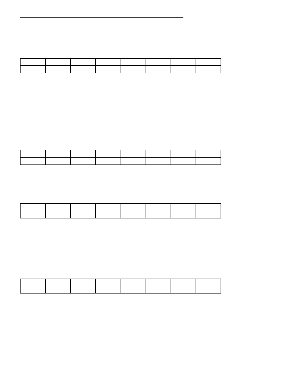
8254 COUNTER 0 DATA - POST TRIGGER CONVERSION COUNTER
BASE + 12
Example, 30Ch, 780 decimal
READ/WRITE
D1
D2
D3
D4
D5
D6
D7
D8
0
1
3
2
4
5
6
7
Counter 0 is used to count conversions to stop the acquisition when a known number of samples have occurred. It essentially is
gated on when only a 'residual' number of conversions remain. The main counting of samples is done by the Interrupt Service
Routine, which will increment each time by 'packets' equal to Fifo 1/2-full (Fifo 1/2-full is 512 for DAS6400). Generally the value
loaded into Counter 0 is N mod 512, where N is the total count, or the post trigger count, since Total count is not known when
pre-trigger is active. Counter 0 will be enabled by use of the ARMED bit (Base+8) when the next-to-last 1/2-full interrupt is
processed.
Counter 0 is to operated in Mode 0.
8254 COUNTER 1 DATA - PACER DIVIDER LOWER
BASE + 13
Example, 30Dh, 781 decimal
READ/WRITE
D1
D2
D3
D4
D5
D6
D7
D8
0
1
3
2
4
5
6
7
8254 COUNTER 2 DATA - PACER DIVIDER UPPER
BASE + 14
Example, 30Eh, 782 decimal
READ/WRITE
D1
D2
D3
D4
D5
D6
D7
D8
0
1
3
2
4
5
6
7
Counter 1 is the lower 16 bits of the 32-bit pacer clock divider. It's output is fed to the clock input of Counter 2 which is the upper
16-bits of the pacer clock divider. The clock input to Counter 1 is a precision oscillator source, selected by software to be 1MHz or
10MHz
Counter 2's output is called the 'Internal Pacer' and can be selected by software to the be the A/D Pacer source. Counters 1 & 2
should be configured to operate in 8254 Mode 2.
8254 CONTROL REGISTER
BASE + 15
Example, 30Fh, 783 decimal
WRITE ONLY
D1
D2
D3
D4
D5
D6
D7
D8
0
1
3
2
4
5
6
7
The control register is used to set the operating Modes of 8254 Counters 0,1 & 2. A counter is configured by writing the correct
Mode information to the Control Register, then the proper count data must be written to the specific Counter Register. The
Counters on the 8254 are 16-bit devices. Since the interface to the 8254 is only eight bits wide, Count data is written to the
Counter Register as two successive bytes. First the low byte is written, then the high byte. The Control Register is eight bits wide.
Further information can be obtained on the 8254 data sheet, available from Intel or Harris.
24