7 interrupt and pacer control register – Measurement Computing CIO-DAS6402/12 User Manual
Page 24
COMPATIBLE MODE:
Write to Base + 8 only clears the interrupt flip-flop (sets CLRINT only (= 1)).
5.7
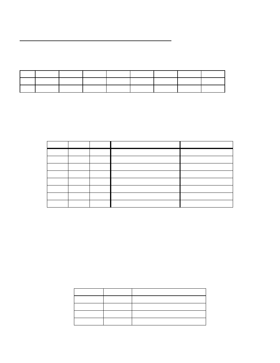
INTERRUPT AND PACER CONTROL REGISTER
BASE ADDRESS +9
Example, 309h, 777 Decimal
READ/WRITE
HC_PS0
HC_PS1
DMAEN
XINTE
HC_IS0
HC_IS1
HC_IS2
INTE
COM
HC_PS0
HC_PS1
BURSTE
XINTE
HC_IS0
HC_IS1
HC_IS2
INTE
ENH
0
1
2
3
4
5
6
7
INTE
=1, Analog Interrupts are enabled, =0, interrupts are disabled.
The system interrupt level is determined by the three HC_IS0-2 bits. The interrupt source (Single AD, FIFO Half-Full, End of
Burst) is selected by the two Analog Interrupt Source bits HC_AI0 & HC_AI1 (Base + 11). Use of external interrupt (XINTE) also
requires that INTE = 1.
HC_IS2, HC_IS1, HC_IS0 will map an enabled interrupt onto a specific ISA bus interrupt level. See Table 6-4 below:
Table 5-4. Interrupt Levels - Enhanced & Compatible
7
7
1
1
1
6
15
0
1
1
5
5
1
0
1
none - see Note
10
0
0
1
3
3
1
1
0
2
2
0
1
0
none
11
1
0
0
none
none
0
0
0
Compatible (ref)
Interrupt Level- Enhanced
HC_IS0
HC_IS1
HC_IS2
Note: Some Interrupt levels in Enhanced Mode are different from Interrupt levels in Compatible Mode. IRQ4 was dropped from
the Compatible-mode IRQ's to allow a single GAL to decode all IRQ's, and since COM1 uses IRQ4, the DAS1600 will probably
never use it.
XINTE: =1, External Interrupt enabled. =0, External Interrupt disabled. The external interrupt is a direct digital path from the
100-pin connector to the system interrupt. External Interrupt shares the Interrupt Level with the Analog Interrupt path. (Only
enabled in Enhanced mode).
BURSTE When = 1, Burst Mode is enabled. When = 0, Burst Mode is disabled. The number of channels in the burst is
determined by the Mux Hi/Lo register.
(BURST Mode also enabled by write to BASE + 406hex bit 6 as on DAS1600 series).
HC_PS1, HC_PS0:
Controls the source of the A/D conversion Pacer according Table 6-5 below:
Table 5-5. Control Source of A/D Conversion Pacer
Internal Pacer (8254)
1
1
External Pacer Rising Edge
0
1
External Pacer Falling Edge
1
0
Software Convert
0
0
Pacer Source
HC_PS0
HC_PS1
20